TPS25751: Guidance Needed: Generating .bin for TPS25751 Without TI Hardware

Part Number: TPS25751
Other Parts Discussed in Thread: USB2ANY

Tool/software:

Guidance Needed: Generating .bin for TPS25751 Without TI Hardware

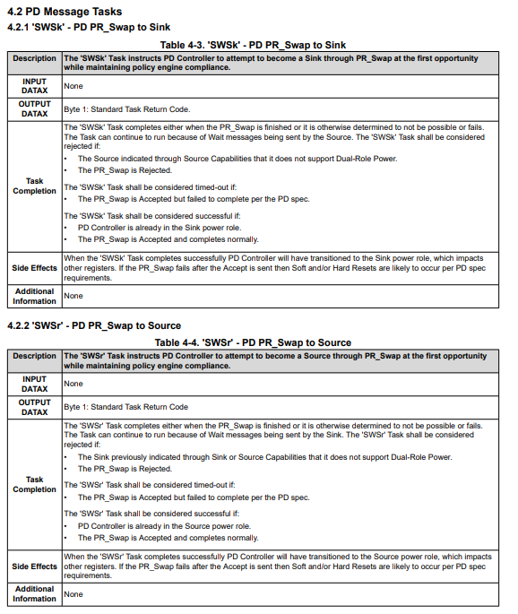
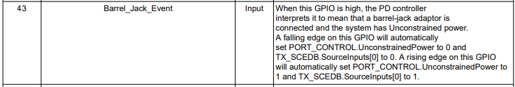
In my design TPS25751SRSMR , and also connected EEPROM (24LC512-E_SN) , I want to operate in DPR , and want to use GPIO 0 as input to switch the role from source to sink. My PCB is ready and mounted with components. GPIO 0  will sense 3VDC to take the decision. Please help me with the following 

Schematic TPS25751.pdf

I am working with the TPS25751 and need to generate a .bin (or equivalent flash image) for EEPROM programming based on my configuration settings.

I have installed the USBCPD Application Customization Tool (v1.1.1) and created the required project, including GPIO mappings and PD sink configuration. However, I face the following challenges:

  1. The “Build Project / Generate Binary” option is not available in my installation 

  2. I am currently using a third-party USB-to-I²C bridge (FT200XD / CJMCU-200) which the tool does not recognize.

  3. The tool shows an error: “Error: failed to connect: no port found” — preventing me from generating the output file.

  4. My goal is only to generate the configuration .bin file (or .json / .hex) that I can later program into EEPROM using my own method, without needing TI hardware like USB2ANY or an EVM.

  • Hello Abhijit,

    Thank you for reaching out.

    The “Build Project / Generate Binary” option is not available in my installation 

    From my understanding you want to generate a full flash binary using the USBPD Application Customization Tool. First, make sure you complete the questionnaire.  Click on the "Export" drop down located in top right corner of the customization tool. If the drop-down options are grayed out, you may not have all the questions answered.

    I am currently using a third-party USB-to-I²C bridge (FT200XD / CJMCU-200) which the tool does not recognize.

    Unfortunately, the tool will not be able to recognize a third-party bridge device. 

    The tool shows an error: “Error: failed to connect: no port found” — preventing me from generating the output file.

    You are able to generate an output file without being connected to the hardware.

    To fix the "Error: failed to connect: no port found" message navigate to Options -> Serial Port Settings. Ensure you are connected to the desired COM port. Reconnect the Hardware connection by double clicking the link image in the bottom right corner. You should receive a "Hardware Connected" confirmation in the bottom right corner. 

    GPIO 0  will sense 3VDC to take the decision.

    The type of GPIO trigger events is fixed for this device. For the design choice stated above, can you please clarify which of the GPIO event you intend to use? The event names can be found in the TPS25751 TRM Table 5-2.

    Below is the TRM:

    TPS25751 Technical Reference Manual (Rev. A)

    Thank you, 

    Katilynn

  • Thank you for your reply -- 

    Yes when i click Export - drop-down options are grayed out. 

    I do not have "USB2ANY" OR the evaluation board of TPS25751.

    I have the PCB of which i have shared the schematic.

    "GPIO event you intend to use" - Barrel_Jack_Event 

    and

    "GPIO Event Polarity as" - Inverted Event 

    Kindly let me know if any other input is required

    Request to please help -

  • Hello Abhijit,

    Thank you for your response.

    Since the drop-down options are grayed out, we need to make sure all questions are filled in. Are you needing clarification on how to answer specific questions on the questionnaire? 

    I do not have "USB2ANY" OR the evaluation board of TPS25751.

    To reiterate, you do not need to have your hardware connected to the customization tool in order to export a binary file. 

    "GPIO event you intend to use" - Barrel_Jack_Event 

    and

    "GPIO Event Polarity as" - Inverted Event 

    To configure this GPIO event with our tool:

    1. Enter Advance Configuration mode

    2. Scroll down to IO Config (0x5c0)

    3. Click on GPIO 0

    4. Select "barrel_jack_event (43)" for the GPIO Mapped Event

    5. Select "Inverted Event" for the GPIO Event Polarity

    For the GPIO event, are you wanting to use GPIO0 or GPIO1? In the schematic your GPIO0 is connected to GND and GPIO1 has connections for a trigger event.

    Thank you,

    Katilynn

  • Thank you very much for your reply  ... 

    "we need to make sure all questions are filled in" - Your suggestion worked now the drop-down options are visible 

    "For the GPIO event, are you wanting to use GPIO0 or GPIO1"  - Yes we are using GPIO1 . 

    Please confirm once i do your suggested setting "To configure this GPIO event with our tool:"

    When GPIO1 Gets input of 3VDC when 9VDC is present (With R3 and R4 divider) , TPS25751 will change the PDR role from source to sink and Pin 21 Gate_Vbus will be set low.

    GPIO1 > 3 V (HIGH)PD Sink

    GPIO1 = 0 V (LOW) ⇒ PD Source

    Requested to please suggest 

  • Hello Abhijit, 

    Thank you for your reply.

    I will get back to you on the confirmation of the trigger event behavior by then end of tomorrow. 

    Thank you,

    Katilynn 

  • Hello Abhijit, 

    Thank you for your patience.

    GPIO1 > 3 V (HIGH)PD Sink

    GPIO1 = 0 V (LOW) ⇒ PD Source

    I went ahead and tested the behavior of the barrel_jack_event. Once the GPIO event triggers HIGH, a singular power role swap occurs. Toggling the GPIO pin LOW will not switch the power roles back to a source. Unfortunately, there is not a mapped GPIO event that can allow for this toggle between the power roles. 

    If you have an MCU in your system, I recommended using 4CC commands to initiate the power role swaps. 

    See chapter 4 of the TPS25751 Technical Reference Manual:

    Thank you,

    Katilynn

  • Dear Katilynn , 

    Thank you very much for your mail , 

    When " a singular power role swap occurs"

    What will be the condition of ??Pin 21 Gate_Vbus will be set low?? Please answer 

    "Unfortunately, there is not a mapped GPIO event that can allow for this toggle between the power roles. " --> Can use Other free GPIOs - Say GPIO2

    When GIO2 is LOW - GPIO2 = 0 V (LOW) ⇒ PD Source

    As now there is no MCU , only EEPROM .... if it will be required then there will be total design change.

    Requested to please answer.

    Thank and Regards,

    Abhijit Kumar 

  • Hello Abhijit,

    Unfortunately, there is not a mapped GPIO event that can allow for this toggle between the power roles. We will look into the feasibility of adding this feature.

    The TPS25751 will be in dead battery mode upon powering up from VBUS only (ie. VIN3V3 is unavailable). When the Barrel_Jack_Event occurs the dead battery flag is cleared on the GPIO rising edge allowing for the power role swap to occur.  This event is typically used in applications where VBUS power is available prior to VIN3V3.

    What will be the condition of ??Pin 21 Gate_Vbus will be set low??

    Gate_Vbus is set low temporally as the source stops supplying VBUS to the sink. Once ports do the power role swap, the new source will apply voltage over VBUS and GATE_Vbus will be set high at the necessary voltage on VBUS.

    Thank you,

    Katilynn

  • Dear Katilynn , 

    I think that is am left with no other option , I will have to add MCU in our current design (OR any other suggestion you can make)

    Before that please answer my below query -

    Can use Other free GPIOs - Say GPIO2

    When GIO2 is LOW - GPIO2 = 0 V (LOW) ⇒ PD Source

    And GPIO1 will control = GPIO1 = 3V (High) ⇒ PD Sink

    Thanks and Regards,

    Abhijit Kumar 

  • Hello Abhijit Kumar,

    Thank you for your reply.

    Can use Other free GPIOs - Say GPIO2

    When GIO2 is LOW - GPIO2 = 0 V (LOW) ⇒ PD Source

    And GPIO1 will control = GPIO1 = 3V (High) ⇒ PD Sink

    Unfortunately, there isn't a GPIO trigger event where the PD controller initiates a power role swap at this time. Having another free GPIO pin will not allow for the behavior you are requesting. \

    Triggering the "Barrel_Jack_Event" clears a dead battery flag. This allows for the power role swap to be initiated. Whenever the TPS25751 is booted up in Dead Battery Mode, the dead battery flag is present. During dead battry mode, the main voltage is supplied of VBUS from the source and no voltage is coming in through VIN3V3. The TPS25751 can only act as a sink becuase VIN3V3 is not present, and the dead battery flag is still present. Once you add voltage over VIN3V3 and the Barrel_Jack_Event is triggered (i.e the dead battery flag is cleared) the sink can request a power role swap to source.

    With that being said the behavior above cannot be reverse to change the source back to a sink.

    See definition of the trigger event below:

    Like I previously stated, we will look into the feasibility of this feature, but at this time you would need to use a MCU to send the 4CC commands to swap.

    Thank you,

    Katilynn

  • Dear Katilynn , 

    In that case we can plan to use , Arduino Uno(ATmega328P) in our design to configure the TPS25751 , for preferred role swapping .

    I there any ready code for Arduino interfacing with TPS25751

    Thanks and Regards,

    Abhijit Kumar

  • TI USA is on holiday today, please expect delays in response