


Tool/software:
Question from my customer:
In a design that I am working on we are using a TPS57140QDRCRQ to convert a 12V input to a 1V output. The 1V rail is being used to power an FPGA with a tight tolerance window (±3%). The FPGA has a very large window of possible load currents ranging from ~30mA up to 1A.
When I did the design for the converter I had the upper end of this range in mind. We are seeing now that at very light loads (30mA to ~300mA) the converter is operating in what we believe is the "eco mode". I have the following questions for you and your team.
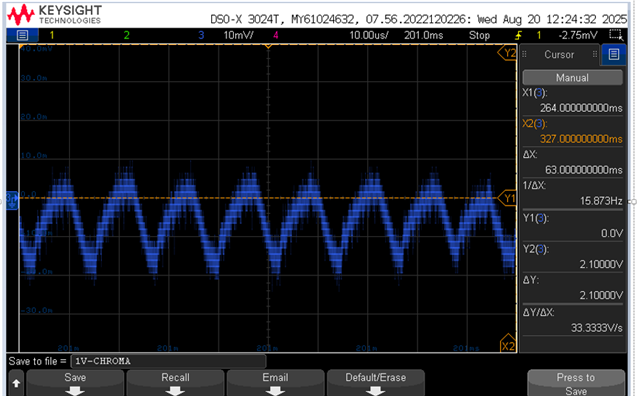
1. Can you confirm that what we are seeing here is the Eco mode in action? (the scope is AC coupled to take this measurement)
2. how much inductor ripple current does the IC need for robust operation of the control loop? I am using a 10uH inductor and we have some concern that the ripple current at light load may be too small for the control loop to operate well.
3. Is there a way to turn off the "eco mode" in this part or is there a pin compatible part that does not have any light load efficiency saving features?
Thank you!

