LM51561-Q1: Abnormal waveform

Part Number: LM51561-Q1

Tool/software:

Dear team,

During the application of TI LM51561-Q1 in SPEIC circuits, overcurrent damage may occur in D400 (using VSS8D3M15HM3-H, If3A, Ifsm60A) when powered on (different power supply models may have different results). L400 uses B8247D6223M603.

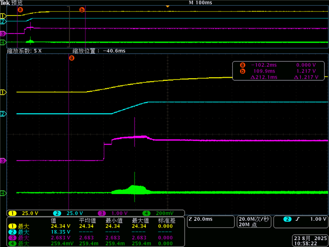
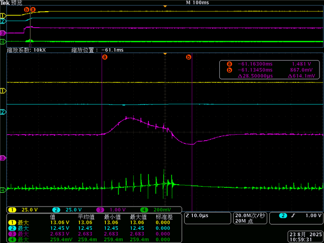
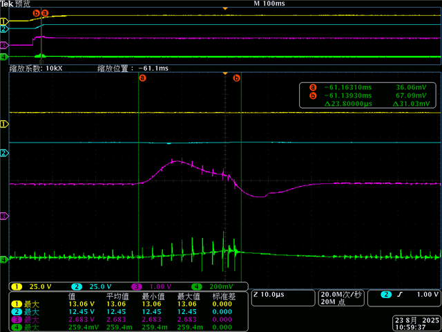
The schematic diagram and test waveform are as follows: yellow is the voltage of the diode D400, red is the voltage of the chip FB pin, and blue is the current of the diode D400.

Could you please help analyze the cause of the abnormality?

  • Hi Allen,

    Thanks for reaching out.

    Can you please fill out the quichstart calculator? This will make the schematic review easier. 

    Also can you please attach waveforms of the switch node, Vin, Vout,COMP and CS pin?

    Best regards

    Moritz

  • Hi Moritz,

    Please check the test waveform, yellow line V_PMOS_KL30-1, blue line VDD_18V, red line COMP, green line CS.

  • Hi Allen, 

    Thanks for the picures. I see the waveform of the switch node is missing. Can you please add it instead of Bias voltage?

    The CS signal should be measured with a very short GND connection. Also the resolution should be ~20mV per division.

    In the waveforms you sent, can i see the failure case? Does the diode get damaged in this case?

    Does the output reach the value it should? It is hard for me to interpret the pictures.

    Please also fill out the attached calculator: https://www.ti.com/tool/download/SNVR481 

    Best regards

    Moritz