TPS274C65: Use of BS version in daisy chain mode

Part Number: TPS274C65

Tool/software:

Hello,

I am looking at using two TPS274C65BS devices in a SPI daisy chain with 24bit mode. I understand, the connection of the DSPI pin as well as the SPI connection between the devices and the master.

However I am not exactly clear on how the data transfer from the devices (slaves) to the master happens.

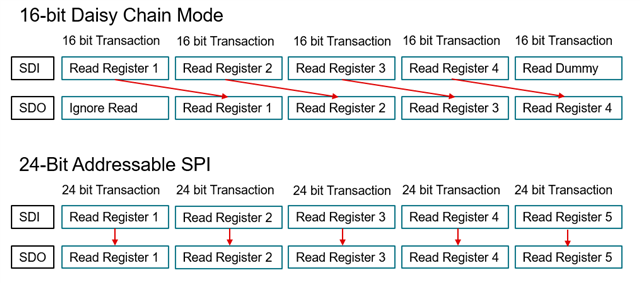
From the datasheet, it looks like the TPS274C65BS normally sends it data out (or response) simultaneously (or in the same 24bit cycle) as the data is received (the command) from the master. I.e. Figure 8-13 in the datasheet for a read.

However, in a daisy chain the TPS274C65BS has to shift the data received on the SDI pin to the SDO to be transferred to the next device. Therefore it cannot sent its data (or response) at the same time.

Does the TPS274C65 send its response on the next clock cycles?

Which means that for a daisy chain of two TPS274C65 devices in 24 bit mode, the first 48 clock cycles are used to send the commands to the two devices and another 48clock cycles are needed to receive the responses from the slaves (96clock cycles in total)? Or are 3x24 clock cycles required to get all the responses?

Maybe a more detailed diagram of two read commands (and responses) of two devices in 24bit daisy chain mode would be helpful.

Many Thanks & Best Regards,

Guillaume 

  • Guillaume,

    Your understanding is correct: for the daisy chain configuration you essentially have to do a double transaction: one write transaction to specify which address to read and a second transaction to read payload. I will look through our design architecture guide to see if we have a more clear diagram that specifies this.

    Alternatively, we do have an addressable SPI mode where it would simplify the reads a bit more. We have an EVM and reference source code available at:

    https://www.ti.com/tool/TPS274C65USBEVM

    Best Regards,
    Tim 

  • Hi Tim,

    Thanks for your response.

    Ideally, we would like to stick to using daisy chain mode because 1. it saves us on data/control lines that have to go through isolators 2. it allows to "synchronize" the outputs of the two devices on the daisy chain as I assume data from the shift register is loaded on the CS low>high transition meaning the outputs from the two devices would switch at the same time.

    The key point being how long it takes to send and receive the data from the two devices and I couldn't really see from the datasheet when/how the data out was happening.

    Did you manage to find the diagram in the architecture guide?

    When you say two transactions, you mean keep clocking the devices without sending any data from the master (i.e.CS stays low the whole time)? Or does the Chip select need to transition from low to hi to initiate the response (i.e. the device responds on the next SPI frame)?

    I have ordered some eval boards to play around with.

    Best Regards,

    Guillaume

  • Hi Guillaume,

    Thanks for your response, one of our engineers will help provide some clarity early this week.

    Thanks,

    Alek Kaknevicius

  • Hi Guillaume,

    Please see a better sequence diagram for daisy chain below:

    In daisy chain mode, the read output is delayed from the read request by one SPI frame as Tim mentioned.

    CS doesn't need to be toggled between SPI frames within each transaction, since you want all of the devices to be synchronized as to when they latch data during reads and writes.

    So the process would be, for 2 devices:

    - CS goes low

    - 32 clock cycles to send a write to both devices

    or

    - 48 clock cycles to read both devices (num_devices + 1 frames, since the read output lags the read request by 1 frame in daisy chain mode)

    - CS goes high

    etc.

    The last byte in each read SPI transaction can be anything (that isn't read-clear, to avoid unintentional read-clear-ing), since it will be ignored at the beginning of the next SPI transaction.

    Does this help?

    Thanks,

    Patrick