LP5562: Is there an error in the IC that swaps the B_PWM (0x02) & R_PWM (0x04) registers?

Part Number: LP5562

Tool/software:

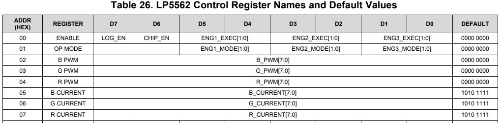
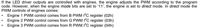
According to the register table, B_PWM is register 0x02 & R_PWM is register 0x04

However, setting the B_PWM changes the RED LED brightness.  Setting the R_PWM changes the BLUE LED brightness.

The B_CURRENT & R_CURRENT are NOT swapped, so I know it's not a hardware issue where they are wired up crossed over.  I have also checked the schematic and confirmed the LEDs are wired to the IC correctly.

I did search the forum but found no mention of this, but I am surprised no one has noticed this issue before.

Cheers

Jason

  • Hi Jason

    Our expert will reply to you early next week.

    Thank and best regards.

  • Hi Jason,

    Can you share us the register setup and schematic for analysis? Thank you!

    We can discuss this question by email, here are my email address: leon-he@ti.com

    BRs,

    Leon

  • Hi Leon,  So, it turns out that the software controlling the LED driver was configured to use the Engines. The following comment is from the Software Engineer.
    I Disabled the engines and I can control the BGR LEDs using Reg 02,03, & 04 respectively.

    I confirmed with the hardware that the layout and connections are done according to the datasheet and are correct.

    Further I found that in datasheet section "7.3.1.2 Controlling LED Driver Output PWM", it is mentioned that


    So, we have all engines in direct mode, you can check that by reading the OP_MODE (01h) register.

    Now, if you see the LED map register, we have engines mapped to the LED PWMs. If we read the LED Mapping Register (LED Map) (address = 70h), we have set the value to 0x1b, So E3 is mapped to Blue, E1 to Red and E2 to green.

    So, in direct mode engines will be controlled and not the direct PWMs by writing to the I2C registers, writing to 0x02 will enable E1 which is mapped to red LED and writing to 0x04 will enable E3 which is mapped to blue LED.