TPS6593-Q1: How to configure PMIC to shut down or reset normally through GPIO pins or registers

Part Number: TPS6593-Q1

Tool/software:

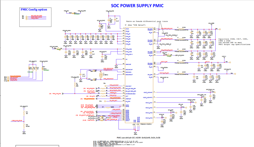
We currently hope to develop a fast power on/off function. PMIC is TPS65931211RWERQ1, SOC is AM62A74AUMSIAMBRQ1


At present, our motherboard will have a supercapacitor EDLC to maintain chip power supply for a period of time during power outages, facilitating the normal shutdown of various modules of the product and releasing resources. The following is the circuit schematic of the supercapacitor part

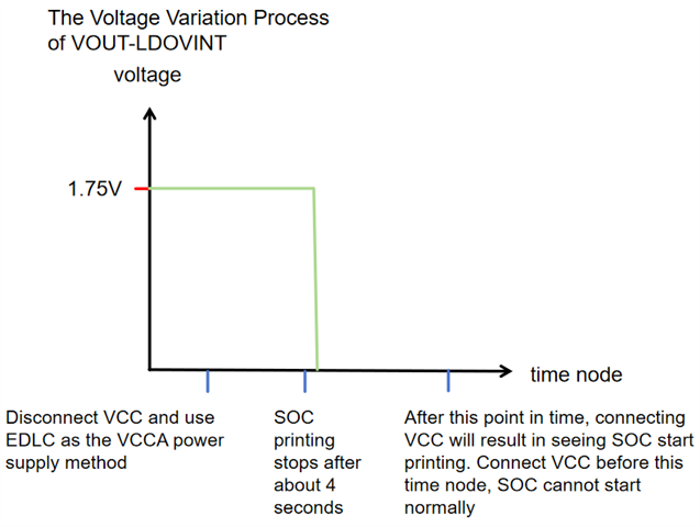
After disconnecting VCC (chip power supply), the supercapacitor begins to discharge for PMIC operation. At this time, when VCC is connected to curve1, SOC cannot start normally.
We need to wait until the supercapacitor discharges to curve2 before connecting VCC to start SOC normally.


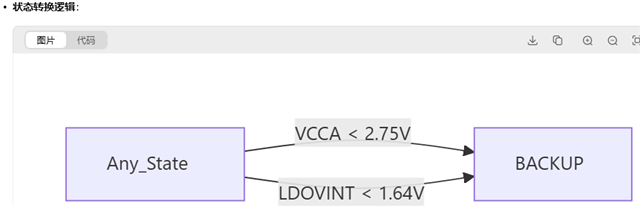
The discharge curve of the supercapacitor is shown in the following figure:

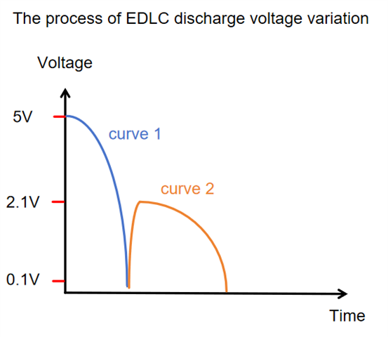
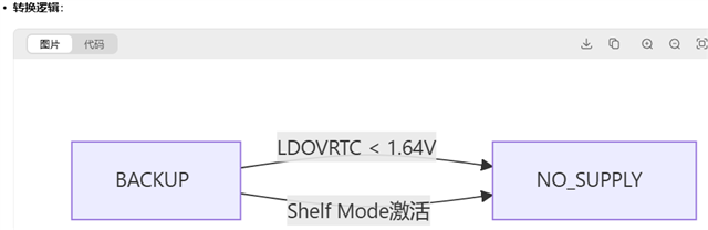
We speculate that PMIC needs a power-off process to achieve reset or normal shutdown, so that it can work properly when connected to VCC and powered on again.


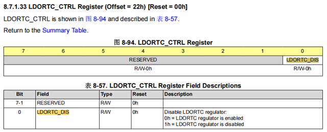
In order to achieve fast power on/off function, we hope to manually control the normal shutdown/reset process of PMIC. Therefore, we would like to know which GPIO or register can be controlled to achieve the normal shutdown/reset operation of PMIC?

P.S.

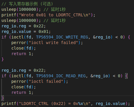
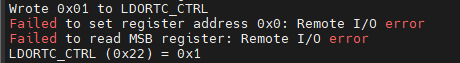
I have tried configuring the SOFT_REBOOT_REGIST of PMIC and writing 0x01 into this register to achieve the software reset operation of PMIC.

But it seems to have no effect. During the discharge process of the supercapacitor, resetting the PMIC, reconnecting VCC for power supply, and SOC also failed to start normally

So I want to know if there are any other registers that can make PMIC shut down/stop working normally

  • Hello Ziming,

    Firstly thank you for the details, the part number for TPS65931211 need VIO_IN (3V3) & VCCA (5V0) are required to be stable during power up and shutdown without these conditions, expectations of how the device will powerup and shutdown can not be said. It is why those input rails to the PMIC are regulated rather than off battery or capacitors.

    Please see the User's Guide here

    Above is an abstraction for the entire state machine, you can see the signal TRIGGER_I2C_0, please look up "I2C_0" in the datasheet for the register write to activate this shutdown signal.

    To wake up the device (if they don't lose power, is to look into the WKUP1 which is tied to GPIO3), but if the device loses power it will need the ENABLE pin to be pulled high again.

    Also be aware of the threshold of VCCA_UVLO this is when the PMIC no longer has the input voltage to maintain internal digital logic power supply so anything less than this will result in a non response PMIC per the datasheet spec.

    BR,

    Nicholas McNamara

  • Hello Nicholas McNamara,

    thank you very much for your reply, but unfortunately, I am unable to see the abstraction for the entire state machine you mentioned
    I guess what you want to show me is this picture.

    Does this image seem to be a PFSM setting? I saw two other state transition diagrams in the detailed data manual. Which diagram should I refer to to to modify the register?

    In Figure 8-36. state diagram for device power states.

    The condition for transitioning from any state (except NO SUPERY) to ACKUP is VCCA<VCCA-UVLO or LDOVINT UVLO condition, and then transitioning from ACKUP state to Initiat state requires VCCA>VCCA-UV.
    1. What is the voltage of VCCA-UVLO?Is it the data mentioned in the table below?


    2. What is the voltage of VCCA-UV?

    Look forward to your reply.

    BR,

    Ziming

  • Hello

    I would like to synchronize the latest debugging progress and problem points

    Firstly, in our circuit design, VCCA is supplied in two ways. When connected to VCC, VCCA is provided by VCC and measures around 4.87V. When VCC is disconnected, VCCA is provided by EDLC.

    According to the state machine transition diagram, it can be concluded that:


    We have 4 situations to consider

     1.Under normal circumstances, the process from NO SUPPLY to connecting VCC for power on is as follows:

    NO SUPPLY——>INIT——>BOOT BIST——>Mission States

     2.If VCC is disconnected and EDLC is used as the power supply for VCCA, and this process is never reconnected to VCC

     3.Disconnect VCC, EDLC serves as the power supply for VCCA, and the VCCA voltage is below about 3.2V. At this point, it can be considered as entering an abnormal working state. What needs to be confirmed here/What I want to ask is

    (1) Is PMIC currently in the BACKUP state?

    (2) From the state diagram, it appears that only VCCA<VCCA_UVLO (2.75V) will enter the BACKUP state. Why is it that SOC printing cannot be seen when VCCA<3.2V is actually measured. Is it possible that PMIC is still in a mission state at this time, but the power supply is insufficient to support the normal operation of SOC?

     4.Connect VCC in an undervoltage state, and VCC serves as the power supply for VCCA. At this point, VCCA is definitely greater than VCCA_UV.

    Why didn't you go through the process of NO SUPERY ->INIT ->BOOT BIST ->Mission States in this situation? It is possible to go NO SUPERY ->INIT ->LP STANDBY. Or it's unclear what state PMIC is in at this moment. Because in this situation, it is not possible to read the registers of PMIC. So what needs to be confirmed is/what I want to ask is

    (1) What is the status of PMIC in this situation? Is it in LP STANDBY or any other state?

    (2) What means should I use to confirm the current status of PMIC?


    Explanation: Any_State=All States Except NO SUPERY


    If the content of the data manual is correct (please help confirm if the following parameters are correct):

    The two ways to switch from All States Except NO SUPERY to the BACKUP state are:

    1 VCCA<VCCA_UVLO(2.75V)

    2 LDOVINT UVLO Condition=LDOVINT < 1.64V

    For method 1, if the measured VCCA is less than 3.2V, the printing of SOC cannot be seen; When VCCA<1.6V and VCC is reconnected, the startup print of SOC can be seen.

    For method 2, VOUT_LDOVINT measures 1.75V when connected to VCC power supply. After disconnecting VCC from EDLC power supply, the voltage remains at 1.75V. After printing stops for 3-4 seconds, 1.75V will drop directly to 0V. It will take about 8 seconds to see the start printing of SOC when connected to VCC.

    If the content of the data manual is correct (please help confirm if the following parameters are correct):

    There are two ways to switch from the BACKUP state to the NO SUPERY state:

    1 LDOVRTC UVLO Condition=LDOVRTC<1.64V

    2.The condition for Shelf Mode enabled is

    (1) In the mission state, let LDORTC_DIS=1

    (2) Immediately reduce the VCCA voltage to 0V (remove the main power supply)

    For method 1, it appears that reconnecting VCC when LDOVRTC<1.64V does indeed result in SOC startup printing.


    For method 2, I can use SOC to write the PMIC register pin LDORTC_DIS=1 through I2C,

    What I want to ask is: how can I set the voltage of VCCA to 0V? When I disconnect VCC, VCCA will be provided by EDLC, so there is no way to immediately drop to 0V.

    Regards,

    Garett

  • Hello Ziming,

    So to answer your questions,

    The second state diagram 8-36 is the generic form, what you see as Mission States is the same thing as PFSM in the diagram as I posted.

    2. What is the voltage of VCCA-UV?

    VCCA_UV is determined by the input of the power supply connect for the TPS65931211, as it is stated in the User's Guide it is not activated by default, but the  LDO1 is used in bypass mode and expects a 3V3 input power supply.

    1. What is the voltage of VCCA-UVLO?Is it the data mentioned in the table below?

    It is the figure named as VPOR_Falling

  •  3.Disconnect VCC, EDLC serves as the power supply for VCCA, and the VCCA voltage is below about 3.2V. At this point, it can be considered as entering an abnormal working state. What needs to be confirmed here/What I want to ask is

    Please see the consideration for the power supplies, as the there are requirements on the PVIN_[LDOn/BUCKn] & VIO_IN with respect to VCCA as I can not determine everything in your system I can not say definitively. If I had to say that as long as the power supply is regulated than I do not see an immediate issue besides the PVIN_LDO12 which has the 3V3 input requirement.

    (1) Is PMIC currently in the BACKUP state?

    Unless the VBACKUP pin is populated, no. The BACKUP state is something having to do with VRTC & it's domain, while the datasheet doesn't make it explicitly clear this is only for the VRTC use and has no bearing on regulation on the power supplies. It is there to ensure the RTC functionality is still running when the main power supply (VCCA) has been turned off.

    Most of the digital logic which includes the PFSM is done off of the LDO_VINT which is powered from the VCCA power input.

    (2) From the state diagram, it appears that only VCCA<VCCA_UVLO (2.75V) will enter the BACKUP state. Why is it that SOC printing cannot be seen when VCCA<3.2V is actually measured. Is it possible that PMIC is still in a mission state at this time, but the power supply is insufficient to support the normal operation of SOC?

    Yes, that appears so, I know I've said it many times, but the input power supply of PVIN_LDO12 could be the cause.

     4.Connect VCC in an undervoltage state, and VCC serves as the power supply for VCCA. At this point, VCCA is definitely greater than VCCA_UV.

    Why didn't you go through the process of NO SUPERY ->INIT ->BOOT BIST ->Mission States in this situation? It is possible to go NO SUPERY ->INIT ->LP STANDBY. Or it's unclear what state PMIC is in at this moment. Because in this situation, it is not possible to read the registers of PMIC. So what needs to be confirmed is/what I want to ask is

    (1) What is the status of PMIC in this situation? Is it in LP STANDBY or any other state?

    (2) What means should I use to confirm the current status of PMIC?

    1) I can not determine the state of the PMIC based upon this statement as I don't know what "VCC in an undervoltage state" means, as to what voltage that is.

    If you can not read the device it may because the pull resistors that the I2C lines depend on are sourced from the PMIC & currently they're not on, also VIO_IN needs to be supplied as well when this occurs.

    2) Using signals from the power up signal would be advisable to see if the device is in the PFSM (nRSTOUT or first signal in a power up), also measuring LDO_VINT as a means to determine if the digital logic is up. See the figure below.

    1 VCCA<VCCA_UVLO(2.75V)

    2 LDOVINT UVLO Condition=LDOVINT < 1.64V

    Since you do not have a power supply on VBACKUP, please just ignore the backup state as it does not apply to you. 

    What I want to ask is: how can I set the voltage of VCCA to 0V? When I disconnect VCC, VCCA will be provided by EDLC, so there is no way to immediately drop to 0V.

    That is for system architecture to implement, not us, this part was designed to work with a single preregulated supply into the PMIC.

    And as for LDORTC_CTRL please do not write to that register, whatever behavior that occurs after performing that write is not defined and we can not make any comments on the behavior.

    BR,

    Nicholas McNamara