UCC5870-Q1: Desat protection not behanig as expected - no action after detecting a fault

Part Number: UCC5870-Q1

Tool/software:

I've connected 2 drivers to IGBTs in a half-bridge configuration as you would to perform a double pulse test. I'm using the circuit to test the desat protection.

I've captured the waveforms for V_DESAT, V_CE (low side switch), V_GE (low side switch) and I_L (current through the inductor). 

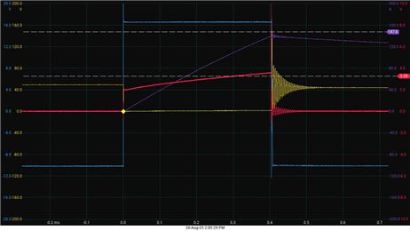
I've set up the desat protection to activate at 3V on the DESAT pin. Table on page 11 says that with a programmed value of 3V the threshold will be set between 2.7V and 3.3V. I've highlighted the point on the plot where V_DESAST crosses 3.3V. Follwing the table, on page 12 it says that the time between fault detection and action is 160ns + t_DESFLT  which is combined a maximum of ~500ns. As seen from the plot, from the moment v_DESAT crosses 3.3V it takes another 100us for the pulse on the gate to go down, and that is because the maximum pulse length on the MCU generating the pulse is set to ~400us.


I've confirmed that the desat fault is signaled by the driver. The MCU reads back the status registers at the end of the pulse and it reads back DESAT and OV faults (OV is expected because the end of the pulse).

In the configuration registers I've confirmed that:
CFG4
 - DESAT_EN pin is set to enable
 - DESAT_DEGLITCH time is set to 316ns

CFG5
 - TLTOFF_STO_EN is set to STO for SC, DESAT nad OC
 - STO_CURR is set to 0.3A (also tried with 1.2A)
 - DESAT_DSCH_EN is enabled
 - DESAST_CHAR_CURR is 0.8mA
 - DESATTH is set to 3V

CFG8
 - GD_2LOFF_STO_EN is enabled

CFG10
 - FS_STATE_DESAT_SCP is PULLED_LOW
 

I've also tried other combinations, using 2LTOFF and normal turn off, but I've saved the settings for this particular measurement.

Is my understanding of how the desast fault protection works wrong or should I be looking for a hardware/software fault?

Best regards,
Šimun

  • Hi Simun,

    Could you include the nFLT1 pin in your waveform capture? That will tell us if there is an issue with the detection or the action.

    Regards,

    Max Verboncoeur

  • Hi Max,

    I did the measurement as you suggested. CHA (blue) is V_DESAT, CHB (red) is V_nFLT1, CHD (yellow) is V_CE and CHE (purple) is I_L

    As the nFLT pin goes low when overvoltage happens it would seem that the issue isn't the action but the detection as you suggested, right?


    The config settings are stated in the post above, am I missing something?

    Thanks,
    Šimun

  • Hi Simun,

    For the sake of being thorough, are you reading back the config values to confirm their state? This behavior could be explained by the DESAT fault being masked or the threshold being set to 3.5V~4V.

    One test that might shed some more light on what's going on is to:

    1. Disconnect the power module so the output does not drive anything

    2. Connect an external supply between DESAT and GND2 and set it to 0V

    3. Drive INP high to enable the output and DESAT comparator

    4. Step the supply on DESAT up slowly until the DESAT fault triggers to see what level & delay the fault triggers with

    Regards,

    Max Verboncoeur

  • Hi Max,

    I did as you suggested and noticed that DESAT protection doesn't activate even when i go to 11V. This pointed me in the direction of masking faults and I found the issue. What I didn't notice before is that the same bit is used  to mask short circuit faults for both shunt based SC protection and DESAT protection.

    Unmasking the fault fixed the issue, and DESAT triggers at the correct, configured level now. 

    Thanks for pointing me in the right direction, mainly to look for an issue in detection of a fault rather than action at the fault.

    Best regards,
    Šimun

  • Hi Simun,

    Glad I could help out!

    Regards,

    Max Verboncoeur