TPS6521905: The issue of chip usage

Part Number: TPS6521905
Other Parts Discussed in Thread: TPS65219, USB2ANY

Tool/software:

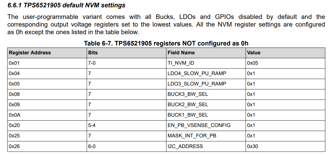
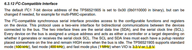
TPS6521905 has no output after being powered on, and the IIC interface cannot communicate.  Does this chip have to be NVM burned before it can be used

What is the default configuration of the EN/PB/VSENSE pins?  Is it EN?  Could you please help me explain?  Please explain in detail these issues as well as the solutions and procedures.  Thank you!

  • Hello, 

    Default configuration of the TPS6521905 is PB configuration. Push button will need to be pressed (falling edge) to enable the device into active mode. 
    However, all Bucks and LDOs are disabled by default. They will not output in active mode since they are disabled. 

    The TPS6521905 is a blank configuration, with all outputs disabled by default, and most register values set to 0h. 
    The NVM should be programmed before expected use. Or toggle the register settings via I2C to check the performance of the device before burning the NVM. 

    The I2C communication should be available once VSYS is supplied, please ensure that you have the minimum hardware requirements as stated in section 2 of the NVM Programming Guide
    Are you using the TPS65219 socket EVM board, or your own custom board?

    Best Regards,
    Sarah

  • We are using a board we made ourselves.  If the device enters the active state, the iic should be able to read the ID register normally.  We use an IIC with a frequency of approximately 200KHz for communication, and the device has no response signal at all

    Could you please help take a look at what the problem might be and how to solve it specifically?Thank you!

  • Hi, 

    Thank you for the context. 

    Are you able to adjust frequency?
    TPS6521905 only supports standard, fast, and fast mode plus (100 kHz, 400kHz, and 1MHz) and VIO level must be 3.3V or 1.8V.

    If there are still issues,

    Check that device address is set to 0x30.
    Are you able to connect a logic analyzer / bus sniffer to the SDA and SCL lines to confirm that the commands are being sent correctly?

    Are you using the TPS65219_GUI with USB2ANY to communicate, or are you using your own IIC communication tool?

    Best Regards, 
    Sarah

  • There's no problem with the frequency and voltage. I don't have a signal generator, only an oscilloscope. It seems that the chip didn't start up normally


    Also, please check the schematic diagram for me

  • Hi, 

    Thank you for the update. 

    Please be aware that a typical schematic review has a week turnaround time. 
    In order to speed up this process, please fill out the Schematic Checklist and mark any areas of concern here:

    https://www.ti.com/lit/zip/slvafe2

    I'll try to get back to you as soon as I can with any comments regarding the schematic.

    Can you verify if the VDD1P8 pin is outputting 1.8 ?

    Best Regards, 
    Sarah