BQ76942: About bq76942 COV protection issues

Part Number: BQ76942
Other Parts Discussed in Thread: BQSTUDIO

Tool/software:

Hi TI  experts,

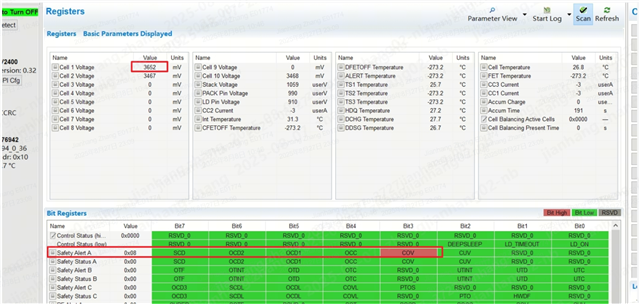
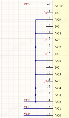
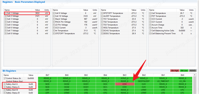
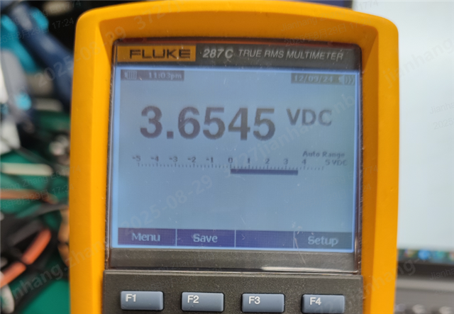
        I've detected an issue with the bq76942. In a three-cell project, the cell overvoltage setting is 3643.2mV. I debugged the single-cell voltage in the first cell to 3652mV, which theoretically triggers a COV fault. However, the register status shows that only Safety Alert A is triggered, not the COV fault in Safety Status A. I need to adjust the single-cell voltage to close to 3670mV to trigger the COV fault in Safety Status A. I debugged only on the Bq host computer (Battery Management Studio) without connecting any other circuits. I tried disabling all Alert registers, but it didn't work. Could the AFE's low number of cell strings affect the accuracy of the single-cell voltage sampling? Please help me figure this out. Thank you.

  • Hello,

    Do you ever notice the voltage being measured at this cell drop below the COV threshold? Or is the measured value staying above the threshold?

    If it does drop, what is your Protections:COV:Delay set to for the device? When an overvoltage event is first detected, an alert signal will be triggered. A fault will only be triggered when the measured value stays above the COV threshold for the time of the delay.

    The lower number of cells will not affect the measurement/detection accuracy of the device.

    Regards,

    Rohin Nair

  • Hi TI experts,

    As shown in the screenshot I sent, I'd like to clarify again that the Cell 1 voltage is 3652mV, stable, and maintained above the threshold of 72*50.6mV=3645.2mV. I maintained the voltage of the first cell at 3652mV for a duration significantly longer than the delay time of 606*3.3+6.6ms, but the COV status in Safety Status A was not triggered; only an alarm was triggered. I raised the voltage to near 3670mV before the COV fault was triggered. This manifests as the overvoltage protection point lagging the set value by approximately 20-30mV.

    In a 10-string design supported by the bq76942, I designed a 3-string application with a voltage sampling resistor of 100R. I'm wondering if the equivalent impedance of VC0-VC1-VC2 in a 3-string application is different from that in a 10-string application, potentially indicating a discrepancy in the protection accuracy of a single cell.

    I look forward to your reply. Thank you.

  • Hello Zhang,

    Are you using two power supplies? And is one supply adjusting the voltage only at Cell 1? Also, can you clarify how you have configured the device for 3S?

    The device must always have cell connections between VC1-VC0, VC2-VC1, and VC10-VC9. Have you configured it this way? This is further explained in Section 16.6 of our datasheet.

    Regards,

    Rohin Nair

  • Hello Rohin,

    Yes, I use two power supplies: one provides a total voltage of 9.9V, and the other is connected to the first cell for independent voltage regulation. The configuration is shown in the attached gg file, with the Vcell Mode setting set to 0203.
    Yes, I referenced the datasheet to design the schematic, as shown in the attached diagram.
    I'd like to know: the overvoltage protection threshold is set to 72*50.6=3643.2mV. I adjusted the single-cell voltage to 3652mV, but the COV fault in Safety Status A was not triggered, or the delay was longer than the set 2s (longer than the 2s). The second cell is particularly noticeable; it takes 3668mV to trigger the COV fault in Safety Status A within the 2s protection delay.
    Do your results using the demo board differ from mine? If so, what are the differences? Please let me know. Thank you.

     PR101.gg.csv

  • Hello,

    That is interesting. Have you compared the actual voltage on the pins versus what is being reported on Bqstudio? If so, what is the discrepancy here? I will test this accuracy on our EVMs and get back to you regarding this.

    Best,

    Rohin Nair

  • RoHin,

    Yes, I tried measuring the input voltage of a single cell pin with a high-precision multimeter and comparing it with the cell voltage readings on BqStudio. I found the error was only 3mV. As shown in the attached image, the cell voltages correspond to nB0-nB1, nB1-nB2, and nB9-nB10, respectively.
    My cell sampling resistor is 100R, but I tried replacing it with a 20R resistor, but it didn't work.

  • Hello,

    That is interesting. The device uses a comparator-based protection trigger, so the error on the actual protections is very small. My initial thought was that the ADC might have been damaged affecting. That would have been the reason why you had to increase the voltage relatively high to trigger the protection, but this does not seem to be the case.

    Can you measure the VC pin, out pin, and REG pin and share the waveform for me? I have demonstrated an example below. The out voltage should drop to 0 when the OVP is triggered. Increase the voltage supply slightly each time over the OVP threshold and let me know at what value it triggers. Measure the delay as well. Your delay is around 2 seconds, so make sure when you are increasing the voltage supply to trigger the fault you are keeping it high for at least 2 seconds before increasing it again.

    The device could actually be triggering a fault for the OVP, but it is not displaying this on BQstudio. We will want to double check this.

    Is there a similar issue like this for CUV?

    Regards,

    Rohin Nair