UCC256404: help on LLC circuit schematic with using UCC256404, UCC28180, UCC24624

Part Number: UCC256404
Other Parts Discussed in Thread: UCC28180, , UCC24624, PMP22087

Tool/software:

Hello expert,

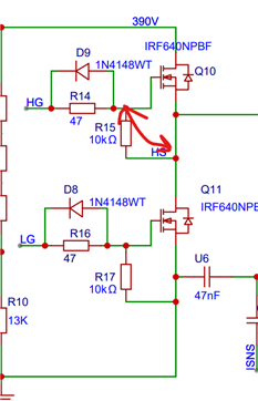
Do you mind helping on checking the schematic attached which is using devices, UCC256404, UCC28180 and UCC24624?

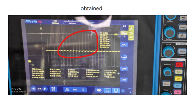
Now this is the case, there is no voltage at rvcc for one second after power up. The voltage at blk does not reach the working point voltage approximately 0.8v, pfc does not boost, the voltage of the main circuit electrolytic capacitor is only 310. And then there's another question, for the UCC256404 circuit, I follow the picture on the chip manual to build the circuit successfully output voltage, but there's a click sound in the circuit operation. As the load current increases, the audible frequency also increases quickly and then goes as fast as the switching power is not working. 5482.LLC.pdf新录音+9.m4a

Best regards,

Wenting

  • Hello Wenting, 

    I support UCC28180 and UCC24624 applications, but I am not well suited to support UCC256404 issues. 

    However, if RVCC is not in spec, then the PFC cannot boost, because VCC for UCC28180 is powered by RVCC.

    If BLK voltage does not rise >1V, then the LLC will not operate, either. 

    I don't know what causes the click sound. 
    However, I noticed in the schematic diagram that both ethe primary and secondary sides have the same GND symbol>
    If the PCB is designed as the schematic is drawn, then there is NO isolation between primary and secondary sides. 

    And if that IS the case, then the AC line voltage may be causing damage to your secondary-side load and/or test equipment if those are not designed to sustain high voltage. 
    Please investigate the Grounding of primary and secondary circuits, and isolate them if that is required. 

    Regards,
    Ulrich

  • Hello Ulrich,

    Thanks for your feedback. The cusotmer follows reference design, PMP22087 to do solution and here are specifications required, 110/220V50HZ VIN24V VOUT. 

    Do you mind helping to loop UCC256404 expert as well?

    Much thanks!

    Best regards,

    Wenting.

  • Hello Wenting, 

    I have looped in someone to support the LLC portion of this thread.  Not sure when he will respond. 

    What is the maximum power level of the 24V, please? 

    PMP22087 has a different ground (SGND) for the LLC secondary output than the ground for the primary side (primary ground is not explicitly named). 
    You customer's schematic shows the same GND symbol for both primary and secondary sides, without any explicit distinction.  Usually this indicates that they are all on the same GND reference and there is no isolation to the output.  
    As I mentioned earlier, please investigate this and correct it if it is true.

    Regards,
    Ulrich 

  • Hi, I work on UCC256404. Can you please provide me the design calculator for LLC section so that I can understand the problem? For sound, can you please confirm the sound is coming at only burst mode or out of the burst mode or throughout the operation?

    Also, what Uli mentioned, please give two different grounds for primary ground(PGND) and secondary ground(SGND).

    Regards,

    Sougata

  • HI Sougata,

    Thanks for your feedback. 

    At present, the rectification of GND has been completed, and the problem is still abnormal noise. Through the oscilloscope, we can see that the output of the chip is a PWM signal with 50% duty cycle to control MOS, and then there are a lot of empty periods. Here is the problem of abnormal noise.

    Is there any way you can help my customer?

    Best regards,

    Kyle

  • Hi Kyle, 

    Can you please provide the design calculator of the LLC controller and oscilloscope results comprising LO, HO, Resonant current, switch node when the problem you are seeing?

    Also, mention at which Vin, Vout and load current you are seeing the problem?

    Regards,

    Sougata

  • Hi Sougata,

    Oscilloscope waveforms need to be available next week. The calculation design is basically consistent with the annex.

    I will answer your other questions as follow:
    1. The waveforms of lo and ho are about 50% duty cycle complementary waveforms, but their amplitudes are different, and ho's is higher. They only work in rapid alternation for a short period of time, and there is no waveform at other times. The customer also measured the value of VCR and the value at the transformer pin, and their waveforms were very chaotic.
    2. This audible noise basically appears in any input and output, including 220V input voltage, 24V output voltage and 18V output voltage. After loading, the frequency of the sound will be higher, and the efficiency is very low, which is only about 70%. The transformer and resonant inductor are seriously heated. It was suspected that the voltage was insufficient, but the measured voltage at the capacitor was relatively stable.
    3. It is worth mentioning that in the initial circuit board, when the optocoupler feedback is abnormal (it is 0 when the pin voltage of 431 is measured at 2.5v, but there is no output when it is removed), but the output voltage will decrease with the increase of load, but the circuit has no abnormal sound. Now this circuit board has also changed and tested some operations on FB pin, but the results have not changed. 

    4774.UCC25640x Design Calculator Rev4.0.xlsx2112.LLC.pdf

  • Hi Sougata,

    Have you made any new progress here? The waveform needs to be sent to me by the customer later.

    Best regards,

    Kyle

  • Hi Kyle,

    Understood. But is is really difficult to comment without oscilloscope waveforms.

    However, based on your observations, 

    I will recommend to check these things:

    1. As High side and Low side gate voltage is different, please check what is the voltage level for both the waveforms. If low side fet is having less gate voltage that means VCC OF UCC256404 is not properly given.

    2. Please provide waveforms for FB pin voltage along with LO, HO, Resonant current, switch node? Is FB pin voltage going to 0V? If it is, then optocoupler is getting saturated. Please confirm this one.

    Regards,

    Sougata

  • Hi Sougata,

    The customer's oscilloscope waveform has been obtained. Please help me to see what the reason is.3326.LLC.pdf

    Best regards,

    Kyle

  • Hi Kyle,

    1. I can see lot of noise in ground itself. This is somewhat unusual

    2. Please let me know how HO have been measured? What the probe points? And while measuring HO, can you tell the customer to probe following points by a differential isolated probe? Then only HO actual voltage can be measured.


    3. What is the level of FB pin voltage as shown below? Is it lower than 5V? Can they check the FB pin voltage at some load i.e. out of burst mode?

    Regards,

    Sougata