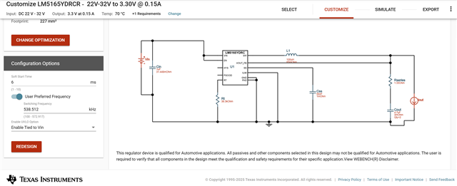
LM5165: Timing Resistor Rt and COT operating frequency

Part Number: LM5165

Tool/software:

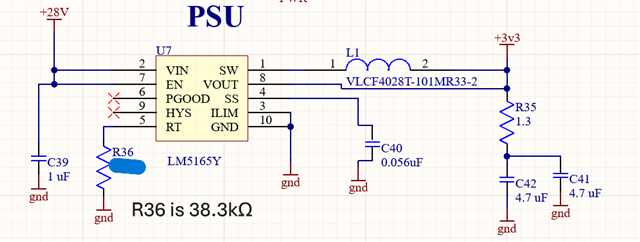
I have a converter (Running in COT Mode)  with Rt=38.3 kΩ, giving an operating frequency of 538 kHz as per TI WEBENCH simulation.

Circuit Parameters:

L=100uH

Rser.=1.3Ω

Cout=4.7uFx2

Vin 28Vdc

Vout 3.3 Vdc

I out 0.135A

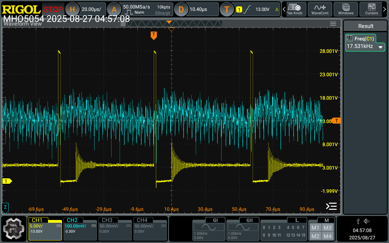
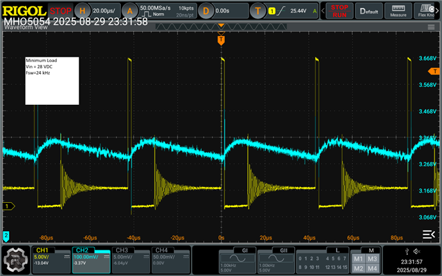
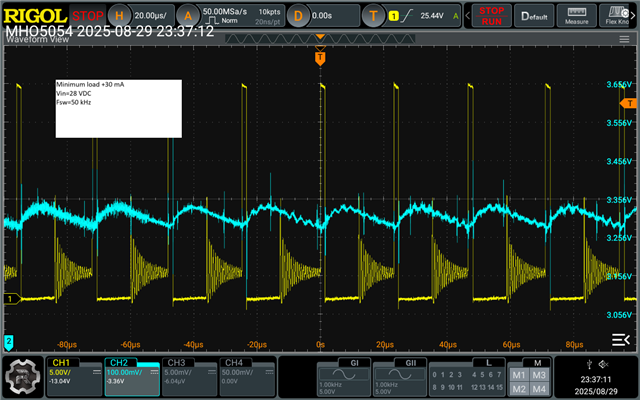
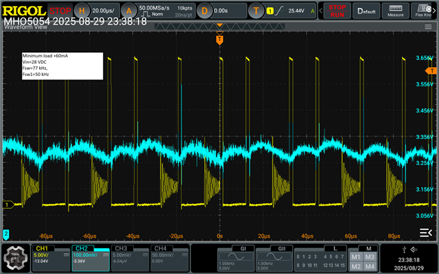
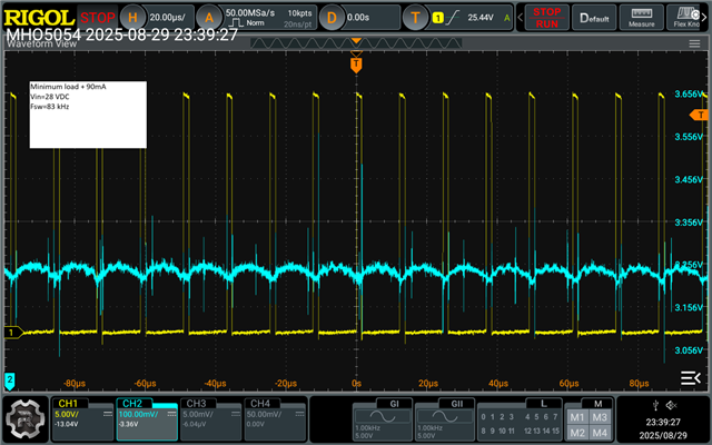
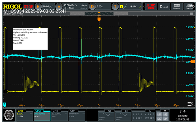
My prototype test fixture is running at 85kHz.

Is this expected? What other changes are necessary to operate the BUCK converter in the 540 kHz range?

  • Hi Greg,

    Can you share your schematic and waveforms SW, Vout, iL for detailed debugging?

    Regards

    Arpita

  •  Simulation.docx

    Attached:

    Schematic

    Simulation

    ~100mA load

    ~10 mA Load

    I am working on getting inductor current waveforms.

  • Hi Greg,

    you have designed inductor and other parameters for 150mA load current.

    As you are operating in low load currents (10mA), it looks like the converter is in DCM mode. Please see datasheet section "7.3.2 Selectable PFM or COT Mode Converter Operation" for light load operation configured in COT mode.

    Configured in COT mode, the LM5165 based converter turns on the high-side MOSFET with on-time inversely proportional to VIN to operate with essentially fixed switching frequency when in continuous conduction mode (CCM). Diode emulation mode (DEM) prevents negative inductor current, and pulse skipping maintains highest efficiency at light load currents by decreasing the effective switching frequency. The COT-controlled LM5165 waveforms in CCM and DEM are represented in Figure 7-4. The PWM on-time is set by resistor RRT connected from RT to GND as shown in Figure 7-2. The control loop maintains a constant output voltage by adjusting the PWM off-time. 

    1. Can you please try increasing the load current further to check if converter goes into CCM mode?

    2. Is Vout regulated to 3.3V? Can you show waveforms?

    3. If you want CCm operation at 10mA also, you need to increase the inductor as well (~330uH).

    Regards

    Arpita

  • Minload is microprocessor

    External load increased in 30 mA increments until regulator goes out of regulation.

    Max switching frequency observed was 83 kHz. Why is this converter not running at 538 kHz?

    Yellow Trace SW

    Blue Trace Vout

  • Hi Greg,

    Could you please double check RT resistor placed on board is correct value? Can you please use RT~121kohms and check if it is able to achieve desired frequency of 160kHZ??

    Regards

    Arpita

  • With the timing resistor set at 121kΩ, the maximum switching frequency is in the range of 100kHz.  Not 160 kHz. How do I get this device to switch at the speeds listed in the datasheet?

  • Hey Greg, 

    What is the value of R35 placed on the actual board? From the Vout waveforms, it looks like ESR (R35) is pretty less. With 1.3ohms of ESR, I expect the Vout ripple to be in phase with IL. 

    How is RT placed on the actual board? Like are you using one resistor or parallel combinations of resistors to get exact value? Could you please double check if some other resistor /component is soldered in RT pin ?  

  • Hey Greg,

    Did you get a chance to check the above points? 

    Regards

    Arpita