TPS650864: PMIC sets Temp_Crit during power up sequence and restarts

Part Number: TPS650864

Tool/software:

Hello,

i am using the TPS6508640 to power my PCBA with AMD Kintex FPGA.

What I notice is that the PMIC restarts its sequence when enabled for 10...100 times (hiccupping) before reaching a state that its sequence is done.
When I readout the I2C registers I get at register 0x05 value 0x01 and at register 0xB4 value 0x13. This means that some sections of the die have reached critical temperature and an emergency shutdown is triggered.
After clearing the bits by writing 1 the values are set back to 00 when I read back the register. Then I start the power down sequence and again the power up sequence. And again the Critical temp bits are set.

I cannot imagine there is realty an over temperature as it only takes 10...12ms between retries. 

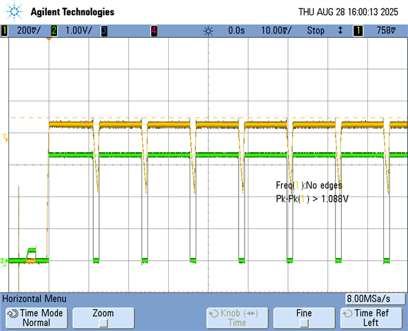
The first step of the sequence is buck2 for 0V85. It enables PG on GPO1 and this continues the chain/sequence.
In the oscilloscope picture yellow is the 0V85 rail of buck2 and green the GPO1 PG_buck2.
By looking at the other PG signal on GPO4 I noticed that GPO1 and GPO4 are going low at the exact same moment and this guided me to an emergency shutdown. And the registers confirmed that it was indeed triggered.
But... why?


  • Hi Eric, 

    Apologies, I may need some more information to determine what is happening here.

    After clearing registers 0x05 and 0xB4, have you also tried clearing the FAULT and SHUTDN bits in 0x02?

    What temperature are you operating the device around, is this truly around T_crit, or is this being mistakenly flagged in the first place?
    When reading 0xB5, are you able to identify which of these regions is exceeding T_hot (and T_crit) ?

    Best Regards,
    Sarah

  • the board is at room temperature, there is no hot area around the PMIC. The PMIC itself is also at room temperature.

    I have at the moment only one board to test, will receive others next week.

    Enable the 12V external power supply and the CTL3 input of PMIC is made high. Buck2 0V85 starts up, the external 5V buck is enabled, buck1 3V3 starts via CTL4, and next buck4 0V9, buck3 1V2 and when buck5 1V8 is ramping up the whole is shut down.

    When I keep CTL4 low so the sequence is interrupted, buck1 0V85 and external 5V are on and stay on. 

    PMIC Reg 00~05: [0, 36, 136, 255, 0, 5]
    PMIC Reg B0~B5: [127, 122, 0, 0, 19, 0]

    reg 02= 136 = 1000 1000 => Fault + SHTDWN are set
    reg 05 = 5    = 0000 0101 => UVLO + CRITTEMP are set
    reg B4 = 19 = 0001 0011 => DIE_CRIT + TOP_LEFT + BOTTOM_RIGHT

    Note on reg 05: when I reset the values by writing FF and then make GPO1 low and high (so power down sequence and power up sequence) the new value of PMIC Reg 00~05: [0, 36, 136, 255, 0, 1] => is no UVLO anymore. I do not see any dip in VSYS or LDO5 or LDO3V3 during the test, so UVLO can be ignored here?


    So when I reset the flags of reg 05 and B4 I read back this:
    PMIC Reg 00~05: [0, 36, 136, 255, 0, 0]
    PMIC Reg B0~B5: [127, 122, 0, 0, 0, 0]

    now I make GPO1 low and high and I read back this:

    PMIC Reg 00~05: [0, 36, 136, 255, 0, 1]
    PMIC Reg B0~B5: [127, 122, 0, 0, 19, 0]

    The critical temperature is set. but my board is at roomtemperature

  • Update....

    sometimes the answer is in front of you. I wrote that the PMIC shuts down while the 1V8 is ramping up. 
    I isolated the loads from the supplies and connected them back one by one. When I reconnect buck5 1V8 to the load the issue comes back. When i put a 'switch' in the 1V8 load and leave it open while the PMIC is doing the power up sequence all works fine. When I close the switch the PMIC enters emergency shutdown and repeats the hiccupping of all rails until a stable situation is found with the 1V8 load still connected. Is there an overload or short circuit triggered in the PMIC...?

    The 1V8 powers mainly the FPGA and that has 3x 100uF MLCCs for VCCAUX, Bank0 and some HD banks. When I remove all 3 caps the PMIC starts up normal. Reading back the registers show no CRIT_TEMP errors. Only the UVLO is set for some reason.

    PMIC Reg 00~05: [0, 36, 8, 255, 0, 4]
    PMIC Reg B0~B5: [127, 122, 0, 0, 0, 0]


    Remains the question why the CRIT_TEMP is set and why the PMIC behaves like this. I cannot find a hint in the datasheet where this is described. Is there some register that can be altered to mitigate the high capacitance on a rail?


  • Hi Eric,

    Due to national holiday in US, most of the experts are out of office today. Please expect delay in response. Thanks for your patience!

    Regards,

    Ishtiaque