Other Parts Discussed in Thread: TPS26750,
Tool/software:
Dear Texas Instruments Support Team,
Thank you for your valuable and prompt response.
In accordance with your recommendations for improved trackability, I have initiated a new thread. For further information, please refer to the previous conversation via the following link:
[Refer to link: https://e2e.ti.com/support/power-management-group/power-management/f/power-management-forum/1544525/tps25751-request-for-guidance-on-suitable-pd-controller-for-simultaneous-charging-and-data-transfer-via-host-usb-type-c-upstream-port-of-usb-hub/6000877]
We would appreciate your detailed guidance on the following points:
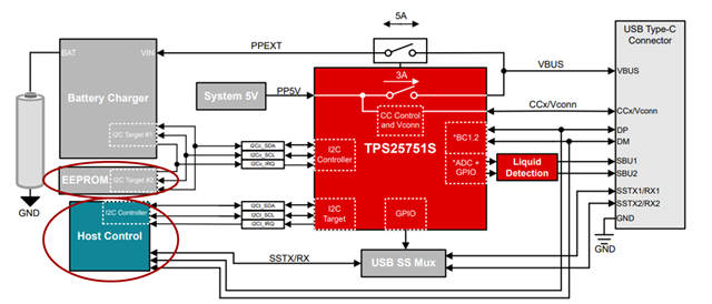
- According to the TI document titled "Application Note for TPS25751 and TPS26750 EEPROM Update Over I2C," please confirm the following connection required for updating the EEPROM patch bundle image via the host MCU.
- EEPROM with I2C Controller of TPS25751 IC
- Host MCU with I2C Target of TPS25751 IC
- Can you confirm if the Host MCU is responsible for updating the EEPROM patch bundle image through the TPS25751 IC? Is this the sole method for updating the EEPROM patch bundle image?
- Is it feasible for the Host MCU to directly update the EEPROM patch bundle image with the EEPROM connected to the TPS25751 IC? If so, please provide a detailed explanation of the process, including example code.
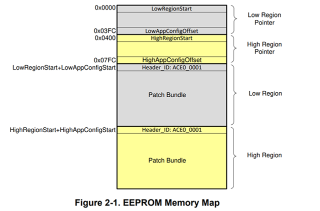
- What is the minimum EEPROM size required for the patch bundle image?
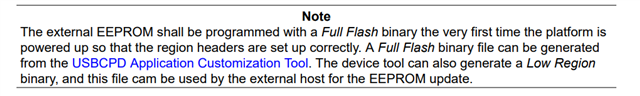
- Could you please clarify the differences between "Generate low region binary file" and "Generate full flash binary file" as presented in the Export section of the USBCPD Application Customization web tool?
- Based on my current understanding:
- The "low region binary file" is intended for updating the EEPROM patch bundle image via the TPS25751 IC through the host MCU.
- The "full binary file" is designed for directly updating the EEPROM patch bundle image via the host MCU.
- Could you please confirm whether my understanding is correct? If not, we would be grateful for your guidance on this matter.
Thank you once again for your continued support and guidance.
Best regards,
Mayank Mirajkar