TLC5940: Symptoms of Vf changes

Part Number: TLC5940

Tool/software:

Hello,

I am an FAE at a distributor that handles TI products.
I received a question from my customers about the TLC5940.
When I use a TLC5940 to illuminate an LED five times in succession, the brightness changes between the first and second illuminations.
There is almost no change in brightness from the second illumination onwards.
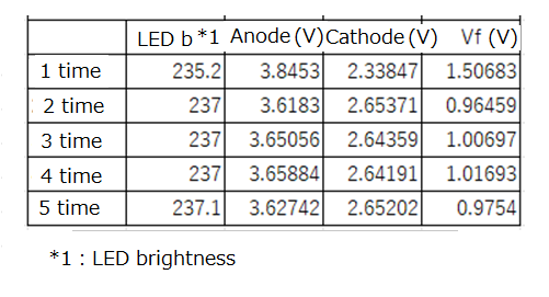
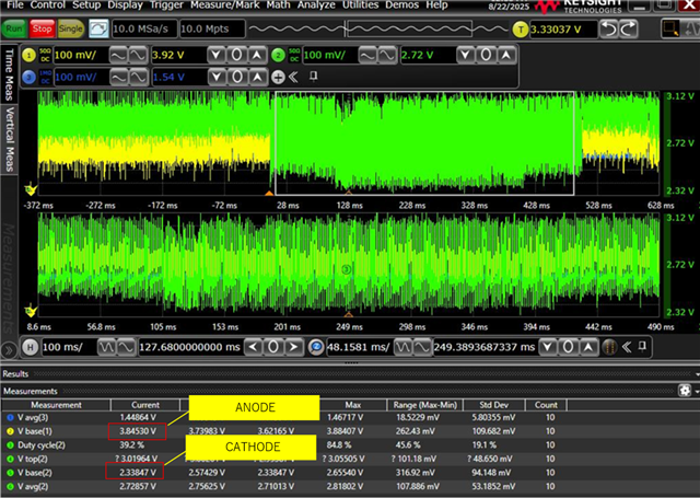
The figure below shows the results of measuring the LED anode and cathode voltage (Vf) after five illuminations.
The LED brightness is the value captured by the sensor when the LED is illuminated.
The conditions for illuminating the LED were the same all five times, but the Vf measured after the first illumination was significantly different.

(Question 1)
Is it possible for Vf to fluctuate even though the GS and DC registers are fixed?
(Question 2)
Even though Vf decreases after the second illumination, the measured brightness increases.
Are there any factors other than Vf that cause the brightness to differ from the second illumination onwards?

Best regards,

  • Hi,

    I'll check and reply to you soon.

    Best regards,

    Jane Ye

  • Hi,

    Could you please tell me how you supply for VLED? Because the voltage on anode is unexpectedly unstable.

    Besides, the forward voltage is lower than it usually should be, so could you also provide the value of GS and DC and the information of LED you are using?

    Best regards,

    Jane

  • Thank you for your reply.

    My customer provided me with the following information.
    VLED is supplied from a DC regulated power supply (4V output) via a charging IC.
    The GS and DC register settings are GS:3079, DC:34.
    The LED used is an IR_LED. Specifications are attached.

    Best regards,

    IR_01.JX.EA0603D88N00.pdf

  • Hi Kaji,

    Thanks for your updating. I might need more follow up information about it.

    May I ask about the test condition of this? If you are using oscilloscope, is it possible to share the waveform of anode and cathode on oscilloscope? Besides, I would like to know that if you have changed the condition of GS and DC settings during the five times of testing.

    Best regards,

    Jane

  • Thank you for your reply.

    The GS and DC setting conditions were not changed during the five tests.
    The anode and cathode were measured with an oscilloscope, but the images were not saved.
    We have asked the customer to take oscilloscope images.
    First of all, based on the current information, please let us know if there are any possible causes.

    Best regards,

  • Hi Kaji,

    Thanks for your updating. I will need to wait for the oscilloscope result for further investigation. If possible, could your customer share the picture with both anode and cathode waveforms?

    Besides, I would like to ask something about the powering up sequence. When you are illuminating five times, did you power off between times? Or have you rewrite any registers? It would be great if you could share more communication details. 

    BRs,

    Jane

  • Hello,

    I received information from the customer about the anode and cathode measurement waveforms.
    The anode/cathode voltage is measured during this period, assuming that the light is exposed for a period between 66ms and 132ms from the start of LED illumination.
    The cathode waveform is PWM controlled, so the voltage during the "L" period is measured, and the anode voltage at that time is also measured.
    In the attached diagram, the anode voltage is 3.53539V, the cathode voltage is 2.65328V, and Vf is 0.88211V.
    Also, regarding the power-on sequence, the power is never turned off during the five times it lights up.
    Also, no registers are rewritten.

    Best regards,

    7674.waveform.pdf

  • Hi Kaji,

    Thank you for your reply and thanks for the waveform you have shared. However, could you zoom in the waveforms in one PWM cycle and put anode and cathode voltage on the same scale? In that case we could see it more clearly and could read the forward voltage more directly on the picture. 

    Besides, could you share how you measured this voltage? It would be great if you could draw a schematic of your LED connection and mark where you put your probe.

    Thanks, and regards,

    Jane

  • Thank you for your reply.

    We are currently checking with you to confirm the information you requested, but have not yet received it.
    It looks like it will take a little time.
    However, in this situation, my customer's investigation will not progress, so could you please tell me what you think the cause of the problem is based on the information you have now?

    Best regards,

  • Hi,

    It looks like in your waveform, the Vf is low at the beginning, and the oscilloscope regard this as V base, so the measurement of anode and cathode might be a little inaccurate. But we still need more information for measuring and further analyzing about this.

    Best regards,

    Jane

  • Thank you for your reply.

    My customer sent me the enlarged waveform below.
    Regarding the measurement method, the cathode voltage is observed just before it enters the LED, and the cathode voltage is observed at the point where it enters the LED driver.

    Best regards,

  • Hi Kaji,

    Thank you for your reply. But I have some follow up questions might need you to answer:

    Sorry I don't quite understand what "it enters the LED" means here. Can you tell me where this anode and cathode is measuring in the waveform? I cannot see where the cursor is in this figure.

    The waveform here is a little hard to distinguish since the channels are overlapped. Could you tell me where is zoomed in figure is in the first waveform? It would be better if you can put two channels in one voltage axis since now, I cannot see the yellow channel clearly and cannot read its voltage information on this figure.

    You said in your question that there is five times of illumination, could you tell me which time of illumination this waveform is?

    Best regards,

    Jane