This thread has been locked.

If you have a related question, please click the "Ask a related question" button in the top right corner. The newly created question will be automatically linked to this question.

LMQ644A2-Q1: spurious

Part Number: LMQ644A2-Q1


Tool/software:

Dear Support Team,

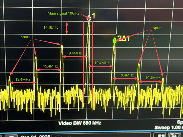
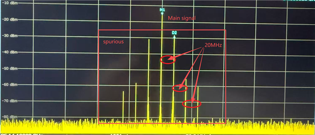
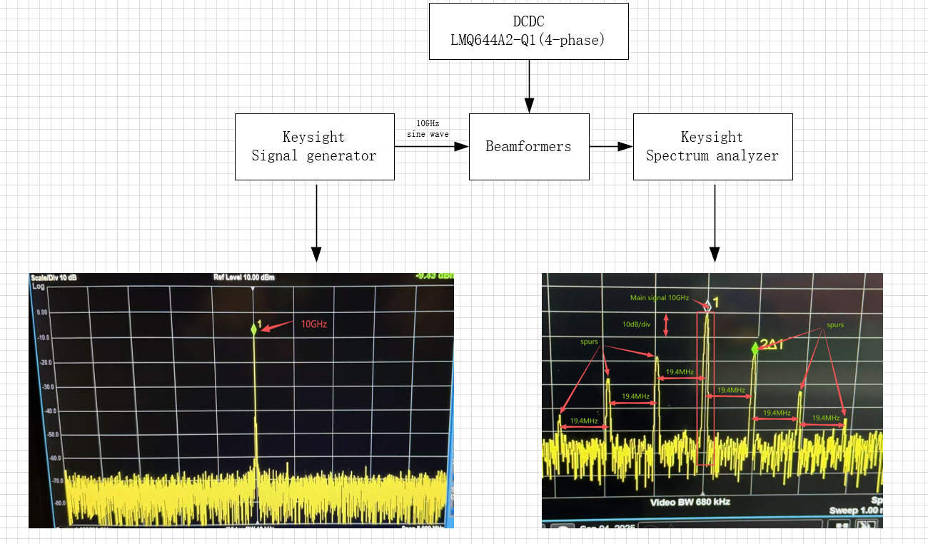
We are currently working on a design using two pieces of LMQ644A2-Q1(4-phase) for generating 1.8V@24A conversion from 24V。There are lots of  RF beamformer ICS supplied by the DCDC circuits. The output current increased as we increase the RF iput power, but when the DCDC ouput current increases to 12A and above, we see some spurious of the output spectrum,they have the following characteristics.

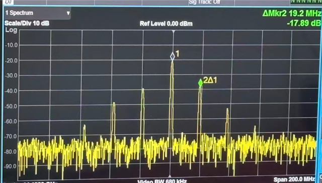
1、About 20MHz、40MHz、80MHz away from the main signal, both upper sideband and lower sideband.

2、The frequency away from the main signal slight changes with the increase of current.

3、The  amplitude of spurious decrease rapidly when we reduce the input power.

4、Modifying the switch frequency does not affect the spurious frequency away from the main signal.

Have you seen this before?  How to remove the spurious?

We appreciate your prompt response and technical guidance,thanks.

Cheng

/resized-image/__size/640x480/__key/communityserver-discussions-components-files/196/spurious.png

/resized-image/__size/3436x2160/__key/communityserver-discussions-components-files/196/2870.Schematic.png

  • Hello,

    Have you tried running the device with spread spectrum enabled?

    As shown, the schematic is set with spread spectrum disabled.

    Is there an input filter to the device? It could have a resonance at 20MHz.

    Best regards,

    Ridge

  • Hi Sir,

    Thanks for your answer. Yes,we tried the spread spectrum mode, but the spurious was still there. Significantly, the spurious spreads too.

    And there are some ceramic capacitors, power inductors, TVS, GDTs on the input of regulators.

    Here is my schematic. Could you please review my schematic and give me some advices?

    /resized-image/__size/640x480/__key/communityserver-discussions-components-files/196/Input-circuits.png

    Best regards,

    cheng

  • Hello,

    Can you provide the part numbers for the components of the filter and an image of the spikes you are seeing with spread spectrum on?

    Best regards,

    Ridge

  • hello,

    Today, I remove all the components of the filter to the device, the frequency and amplitude of spurs remain unchanged.

    Here is the image of the spikes with spread spectrum on, the spurs change a little.

    By the way, is it possible and  the spurs are related to the load, the load impedance is 6 ohm. 

    Confusingly, another design using there pieces of LMQ644A2-Q1(6-phase) for generating 3.3V@36A conversion from 24V, there are no spurs of the

    ouput spectrum. In this design, the beamformer ICS are not the same, and the load impedance is 2 ohm. 

    Thank you for so much fou your suggestions, and I will do my best to Verify them.

    Best regards,

    cheng

    /resized-image/__size/640x480/__key/communityserver-discussions-components-files/196/Spurs.png

  • Hello,

    It is possible that the load impedance is causing the issue.

    Are you able to disconnect the buck IC from the board load, then test with a simple resistive load? 

    That would help confirm if the spikes are a result of the load.

    Best regards,

    Ridge

  • Hello,

    Yes, it is easy to disconnect the buck IC from the board load and test with a simple resistive load. 

    But without the load of beamformer ICS, there will be no spectrum as reference.

    So what kind of information you need when test with a simple resistive load.

    Best regards,

    cheng

  • Hello,

    In that case, then do not test with resistive load. Keep the device connected to the intended load.

    We see that you have tantalum capacitors on the output of the 1.8V EMI filter. Can you move one of those capacitors to the output of the buck converter?

    There could be an LC resonance created between the low impedance ceramics and the EMI filter.

    Best regards,

    Ridge

  • Hello,

    Thanks for your answer.

    Yes, we also concern if there is LC resonance.

    So we remove all the tantalum capacitors and keep the EMI filter, also we remove the EMI filter and the tantalum capacitors, nothing changes.

    What confuses me is that no matter what I do, there are no significant changes of the spurs, especially the frequency of spurs.

    By the way, we also change the output Inductances of DCDC devices, still nothing changes.

    Also, we use another power board of there pieces of LMQ644A2-Q1(6-phase) to supply the same load, the spurs still there, still nothing changes.

    Best regards,

    cheng

  • Hello,

    What is the frequency of the main signal?

    Is it at 20MHz, or are the signals just 20Mhz apart?

    Best regards,

    Ridge

  • Hello,

    The main signal is about 10GHz.

    Best regards,

    cheng

  • Hello,

    I think this has something to do with the load.

    Our device does not have anything which generates a 10GHz signal.

    Aside from the what is shown in the schematic, are there any other capacitors or inductances downstream from the buck converter before the radar chip load?

    can you share an image of the output voltage ripple at both the output of the buck and at the point of load?

    Best regards,

    Ridge

  • Hello,

    I think What I said may not be clear enough.

    Here is the system block diagram. THe 10GHz is the signal we wanted and the spurs are unexcepted.

    /resized-image/__size/2600x1526/__key/communityserver-discussions-components-files/196/7457.system-block-diagram.png

    Yes, every signle chip has four 1nF ceramic capacitors near the power supply pins. There are 32 chips, so that‘s mean 128 pieces of 1nF decoupling capacitors downstream from the buck converter before the radar chip load.

    I have measured the ripple at both the output of the buck and at the point of load using an oscilloscope, the waveform appears to be normal.

    Best regards,

    cheng

  • Hello,

    Since there are no issues on the other board you mentioned, what are all the differences in the load characteristics?

    You mentioned that one set of beam formers has a different load impedance than the other, and you do not see any issues.

    Are there differences in the output filtering, capacitors, or output inductance on that board as well?

    Do you see any spurs on the other board or none at all?

    Best regards,

    Ridge

  • Hello,

    Finally, after many tries, the spurs has been removed  by changing the decoupling capacitors of beamformers from 1nF to 1uF.

    It has nothing to do with the power supply.

    Thank you for your support.

    Best regards,

    cheng