LM25037: How could I increase the soft-start time?

Part Number: LM25037

Tool/software:

Hi,

I designed a 12V – 360V push-pull converter. At the very first startup, the circuit did not start. The hiccup mode was activated and got stuck in it. I had not connected a capacitor to the RES pin, so the CBC was disabled, which caused the hiccup mode to activate immediately. As a test, I soldered a 100nF capacitor to the RES pin. With this, the converter started up and worked properly, but the soft-start time was very short, as shown in the following measurement:

The above measurement was taken with a 100mA load in DCM operation.
My design goal is to achieve at least 150ms soft-start time.
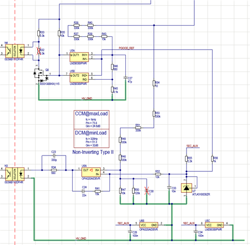
The circuit is shown below:

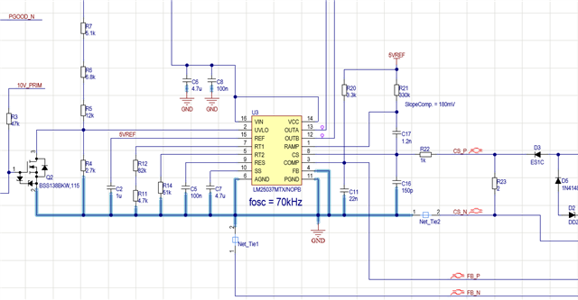
For sizing C7, I used equation (10) from the datasheet. How can I increase the soft-start time?
I was considering placing a PNP transistor between SS and COMP according to the "snvaa44" document. However, as far as I know, in the LM25037 the PWM signals only start once the SS level reaches 1V. The COMP operating voltage can be around 1.2V. This means that by the time SS reaches 1V, the PNP transistor might not be able to perform its function properly.

My other question is: does the soft-start time depend on the load?

  • Hi,

    Soft start time on equation 10 is measured at soft start pin 10, not at the converter output, so when the output load is small the output voltage can reach its regulated voltage much sooner than soft start time based on equation 10. At heavy load, the Vout rise time will be longer. At light load, you can add more capacitors at the output to extend Vout rise time. But this will make heavy load Vour rise further longer. 

    You need to add some external circuit at Vout side. You can provide your full schematics so I can help find how to add.

  • Hi,

    Thank you for your help! The secondary side of the circuit is shown in the picture below.

    An interesting detail is that I used a non-inverting Type II compensator. Perhaps this makes the implementation of the soft-start more difficult. Maybe the Vref should have a ramp-up time?

  • Hi,

    Where is the transformer and associated circuit?

    Please provide your full converter circuit of  LM25037. Your piece by piece circuit is not clear to me how to help.

  • Here is the complete circuit. 
    In the meantime, I’ve also noticed an issue: under higher loads, the supply tries to start, the voltage rises to about 250 V, but then it drops again. The duty cycle keeps fluctuating.
    Interestingly, if I wait long enough after switching it off, it powers on without any problem afterward. But if I turn it off and then immediately back on, it won’t start. With smaller loads, it manages to start right away even after being switched off.
    I handle the on/off switching through the UVLO pin, as shown in the schematic.
    The BC857 shown in the schematic is currently not soldered in. This is already a modification compared to the drawing.

  • Hi,

    One possible way is to add slow down secondary side with the below circuit. C21 would sink current to pull down U12 collector which is connected to COMP of LM25037 to make duty cycle increase slower then the output voltage rising will be slower, so to help extend the soft start time of the output voltage.

    On the problem of rapid re-power on failure, there are some fault conditions triggered, including current, and VCC UVLO off, and (Line) UV. You would need to check all fault conditions to find out then to resolve.

  • Thank you, but unfortunately I cannot apply this method to the current circuit. I would have to build an entirely new compensation network. However, I will probably omit the non-inverting Type II in the new design.