TPS552882: Design check

Part Number: TPS552882

Tool/software:

Hi Teams,

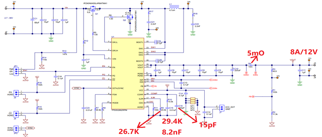
Can the TPS552882 support the following input and output conditions? Vin 9~36V, Vout 12V, Iout 8A.

I tried simulating it using WEBENCH but couldn't get any results, thanks.

Otherwise, I found that when using Webench with Vin 9V and Vout 12V 8A, it shows that the IC temperature is too high.

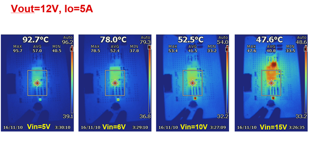
However, we tested with the EVM and the actual temperature was normal (50-60°C). Could you please help confirm if there is any risk in this situation?

  • Hi Che Wen Yeh,

    Thank you for reaching out. With 12V/8A output, maximum average inductor current is 12*8/0.9/9=11.85A. TPS552882 has 16A typical current limit, so from spec side, it is ok.

    Currently I have EVM 12V/5A thermal performance with 400kHz fsw.

    We can see with 10V Vin, IC temperature is around 53.4C. With 9V Vin, 8A Iout, the thermal performance will be worse. I think there might be something wrong with your test. Did you wait for 20min for steady state?

    I recommend to use 200kHz for this working condition. You can modify EVM and do the test with 20 min steady operation.

    Also, you need consider two more factors:

    1. Customer board layout will be worse than EVM. Thermal resistance will be around 1.5 times.

    2.What is the maximum ambient temperature in real application?

    Considering above two factors, you need to reserve some margin.

    May I know what is application here? Will you choose FPWM mode or PFM mode in light load condition?

    Regards,

    Mulin

  • Hi Mulin,

    We conducted tests with an ambient temperature of 50°C. In practice, the duration of maximum current at 9V to 12V conversion is not very long. Currently, only FPWM mode is available, thanks.

  • Hi Che Wen Yeh,

    Recommend to use 200kHz fsw and layout needed to be careful. May I know the MP date for this project?

    Regards,

    Mulin

  • Hi Mulin,

    Get it. Targeting mass production in November 2025.

  • Hi Che Wen Yeh,

    The schedule is very close now. May I know what is the application here? Is there any run rate information?

    Recommend to use 10uH inductor to reduce current ripple. Loop stability must be validated. After you finish you design, feel free to reach out to us for sch and layout review.

    Regards,

    Mulin

  • Hi Mulin,

    We will make the following modifications based on the EVM. Besides changing the switching frequency to 200kHz and the inductor to 10uH, are there any other adjustments needed? Thanks.

  • Hi Che Wen Yeh,

    Recommend to Keep Rlim 20k to reserve some margin for transient occasion.

    Do you use the same Cout part number as EVM?

    Considering current ripple, you can use 400kHz at first and evaluate thermal performance.

    Regards,

    Mulin

  • Hi Mulin,

    Yes, We will use same Cout as EVM. If we keep it at 400kHz, do we need to change the inductor to 10µH? Thanks.

  • Hi Che,

    Yes, you can use 10uH+400kHz at first. For compensation parameters, recommend to use 20k+8.2nF//330pF and do bench test to evaluate.

    Regards,

    Mulin