


Tool/software:
In the project, TPS259474ARPWR is used for power-on control and over-current protection of a power supply.
The schematic diagram is basically the same as the demo reference circuit. The ILM pin is set to a 549Ω resistor, the current limit value is about 6A,
the window capacitor ITIMER is set to 22nf, and the slow-up DVDT capacitor is set to 22nf.
Set the load value through the electronic load, CR mode, the resistance value is 3Ω (I also tried it with a power 3Ω resistor, the results are consistent),
 connect the electronic load to the output of TPS25947, the input is an adjustable power supply of more than 10A, set to 12V, 6A
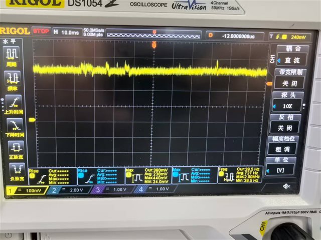
(1) When powered on without load, the 12V output at the out end is normal. At this time, the electronic load is turned on and a 4A load is applied.
The switching load is normal and can drive up to 6A load.
The measured waveform when the ILM pin is 4A is as follows:
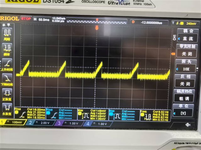
(2) Turn on the electronic load first, that is, with a load of 4A, and then turn on the TPS25947 output.
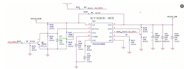
The power-on is unsuccessful. The test voltage waveform of the Ilm pin is 7HZ, a periodic triangle wave of about 150mV.
After debugging, the power-on with load can only drive a load of 2A. If it exceeds the load, it will not work.
The power-on is unsuccessful. There is only a voltage of 0. a few V. When the ILM pin jumps to 4A, the measured waveform is as follows:
The above observation through the ILM pin shows that there is no overcurrent phenomenon when the load is powered on.
Why can't the TPS25947 normally turn on the output after a >2A load is applied, but the chip works normally after being powered on without a load?
PS:
Use the tested adjustable power supply to connect to the electronic load. With the same settings, it is normal to power on with or without load, and there is no problem.
