A related question is a question created from another question. When the related question is created, it will be automatically linked to the original question.
The TPS922050D1 and TPS922051D1 support PWM input signals with ultra-narrow pulse width down to 50-ns for direct PWM dimming. The PWM dimming starts when the DIM input pin is configured by a PWM input signal. When the PWM input signal at the DIM pin turns from low to high, the internal NMOS FET starts switching and the inductor current rises to the determined value set by sense resistor. The LED current is then regulated at the determined value as long as the PWM input signal stays high. When the PWM input signal turns from high to low, the internal FET is turned off causing the inductor current falling to zero. The internal FET maintains off and the LED current stays zero as long as the PWM input signal stays low.
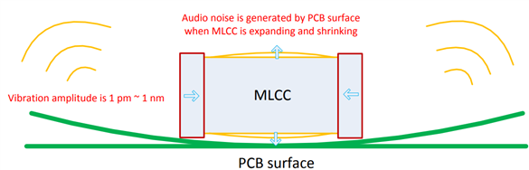
Origin of audible noise:
Multi-layer Ceramic Capacitors (MLCC) is widely used in electronic products due to its good performance, such as small size, low ESR, low cost, and so forth. However, when an AC voltage is applied to MLCC, it expands and shrinks due to the electrostrictive effect of the ferroelectric ceramic. As a result, the printed circuit board (PCB) vibrates in the surface direction as shown below. The vibration of capacitor and board is only about 1 pm – 1 nm, when the vibration frequency reaches the audio frequency range (20 Hz – 20 kHz) of humans, a sound is perceived by the human ear.
The inductor also has similar electrostrictive effect, but it is not common to observe the audio noise generated by the inductor with the advancement of inductor process, especially for the shielding inductor.
Solutions that can minimize or reduce noise to acceptable levels:
The standard range of audible noise frequency is 20Hz to 20kHz. Increase the PWM frequency (out of the audible noise range) to avoid it to be perceived by the human ear. However, as the dimming frequency increases, the achievable dimming ratio will be lowered. Thus, it will be a balance between dimming ratio and audible noise.
Choose the capacitors which do not show piezoelectric characteristics, such as electrolytic capacitor (ECAPs) or aluminum organic polymer capacitors (PSCAPs). However, in some applications, the ceramic capacitors is preferred because of cost or size constraints.
Use quieter capacitors: Ceramic capacitors with low distortion dielectric material; Capacitor with a special mechanical configuration: use metal terminals to mount the capacitor on the PCB board to achieve noise reduction. However, these capacitors tend to be more expensive.
Reduce voltage amplitude variation on capacitors. Use larger output capacitance to lower the AC amplitude.
Use several capacitors with smaller package size since it tends to generate lower noise level with smaller size.
Optimize PCB layout: Use a thicker PCB allows the sound frequency to shift since the weight change; Place the capacitors on top and bottom of the PCB to make the two vibrations cancel each other; Mill holes into the PCB beside the solder pads.