Tool/software:
Dear TI Support Team,
We are facing an instability issue with our LM3477 buck converter design and would appreciate your guidance.
Application details:
- Input voltage range: 23 V – 29 V
- Output voltage: 14.9 V
- Output current (target): 3.5 A
- Switching frequency: ~500 kHz
- Inductor: 10 µH
Observed behavior:
- With Rsn = 12 mΩ, the output current is limited to ~300 mA, which is unexpectedly low.
- With Rsn = 4 mΩ, the output current increases to ~2.5 A, but then periodically drops close to zero and recovers, repeating in cycles.
- The output current also changes with output voltage, and we are not obtaining stable current regulation.
- We attached oscilloscope captures of the sense resistor voltage, as well as our schematic and PCB layout for your review.
Our analysis:
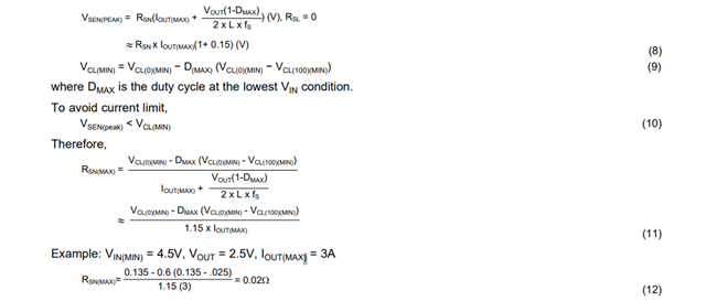
- The expected peak inductor current for 3.5 A load is ~4.2–4.3 A. Based on the current sense threshold (~100 mV typ.), we calculated that an Rsn of ~20–25 mΩ would be more appropriate.
- We suspect that the instability and oscillation behavior might be related to:
- Current sense noise / spikes on the ISEN pin.
- Insufficient slope compensation at duty cycles above 50%.
- Inductor saturation at high current peaks.
- Loop compensation tuning of the COMP pin.
- PCB layout coupling between SW node and sense traces.
- Input supply foldback or droop under load.
Questions:
- What could be the most likely cause of the output instability (periodic drop and recovery of the current) we are observing?
- Could you confirm the recommended RC filter range for the ISEN pin to avoid false triggering?
- What is the typical current sense threshold we should use when sizing Rsn for ~3.5 A load?
- Are there any additional layout or compensation guidelines you would recommend for stable operation with LM3477 at these conditions?
Thank you for your support.WG_MainBoard_V2.1_Battery Charge.pdf


