UCC21551: Inquiry Regarding External Circuit Design for the UCC21551

Part Number: UCC21551
Other Parts Discussed in Thread: UCC21520

Tool/software:

Hello, I'm Cheol-ha kang.

I am a hardware engineer based in South Korea, specializing in the development of converters for the automotive industry.

First, before I ask about the UCC21551, let me briefly describe our topology as follows:

1. Topology : PSFB Converter 

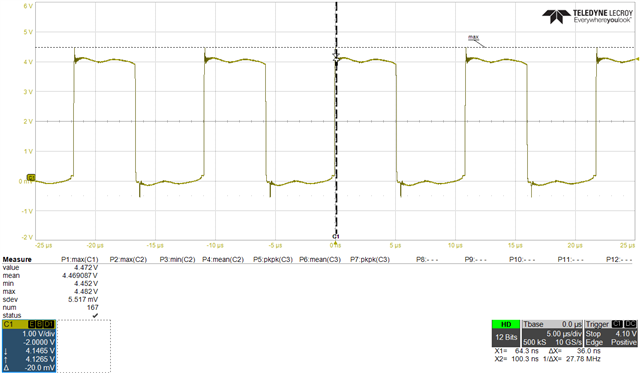
2. Swtiching Frequency : 96kHz 

3. Dead Time : 150ns 
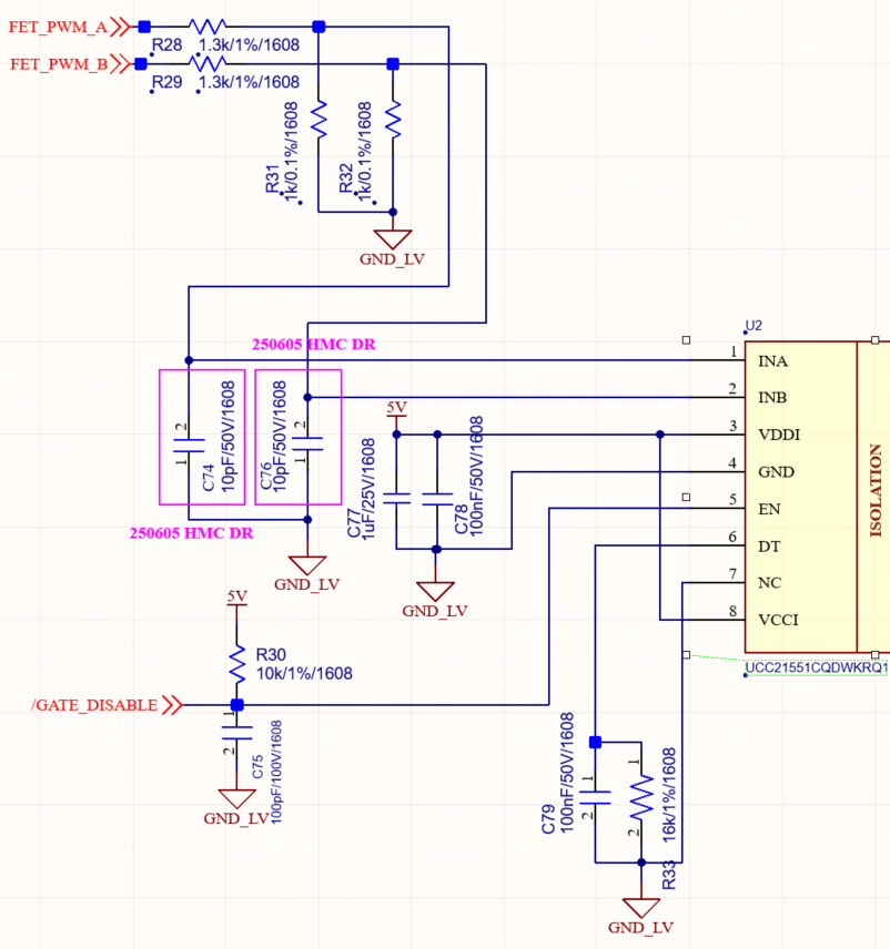
4. Circuit

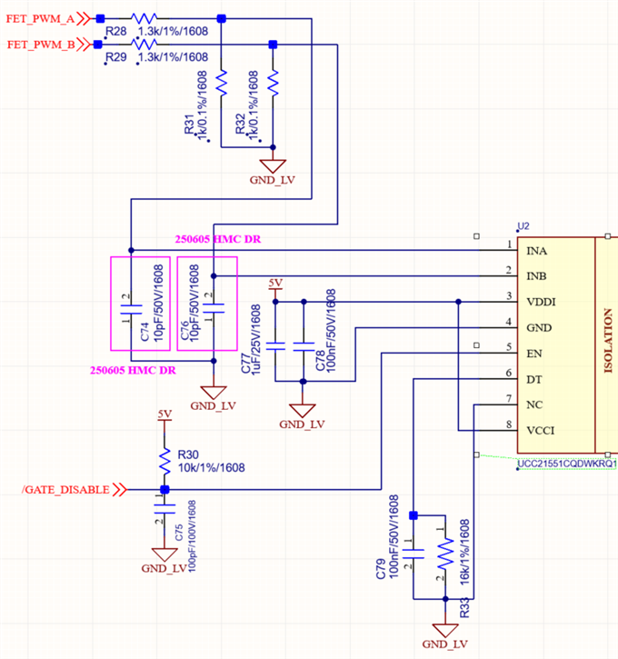
Now for my main question: Will there be any problem if I design the INA/INB input filter like the attached circuit, which is different from the design recommendation in the datasheet below?

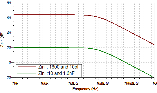
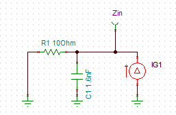
we've implemented an RC filter with 1.6kΩ and 10pF, which results in a cut-off frequency of about 10MHz.

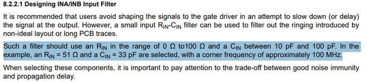
My question is, are we allowed to use values other than those specified in the datasheet's recommendation? I would like an answer on whether it is acceptable to apply our current filter values, even though they deviate from the recommendation, and if this will cause any problems.

I look forward to your prompt response.

thank you.

  • Hi,

    The team is out of office today on U.S. holiday. We will get back to you soon.

    Thank you for your patience.

    Regards,

    Max Verboncoeur

  • Hi Cheol,

    Yes, this will be a problem. I do not recommend more than 100 ohms of filter resistance for your input filter. Could you try a 1.6nF, 10 ohm filter instead? Even though this the RC filter frequency is the same 10MHz as for a 1.6kΩ and 10pF, its source impedance is 160x lower vs frequency, and it will absorb transient noise injection with a much lower voltage rise. Consider a simulation example of a 1A transient injection vs. frequency: 

    Best regards,

    Sean 

  • The PWM source (UCC28950QPWRQ1) in the circuit I designed has a 12V output. Therefore, I used high-value resistors to create a voltage divider. Considering both resistor power loss and the source current, resistors in the range of several kilohms seem to be the optimal choice for my circuit. If you can, please tell me the applicable C (capacitor) values when using resistors in the several kilohm range. and in my opinion, a large RC filter value will just act as a signal delay, and as long as I account for that, it shouldn't be a problem for the design

  • Hi Cheol,

    I see. We have a device called UCC21520 that accepts a 12V input power supply and a 12V input signalvoltage. It is similar to the UCC21551, but it contains an internal LDO to allow >5V inputs. Otherwise, it is P2P compatible. Have you considered using that version instead?

    The recommended max input resistor is 100 ohms. with a 12V input, you would have to use a 240 Ohm resistor in series with a 171 ohm resistor to get a 100 ohm parallel resistance at the input. That is 30mA of current from 12V, which is too much to justify.

    It is just a noise consideration. If you do not have high current noise injection, then >1k resistors and a ~100pF capacitor should be sufficient to prevent input logic errors due to voltage spikes that exceed the input threshold. Hopefully your target input frequency is not >100kHz.

    Best regards,

    Sean