TPSI2072-Q1: Insulation Resistance Monitoring

Part Number: TPSI2072-Q1

Tool/software:

Hello, 

In the datasheet of TPSI2072-Q1, you are presenting 2 different topologies for the monitoring of the insulation resistance (Battery V- reference or Chassis Ground reference). I am interested in the Battery V- reference design, using a B79631 as suggested in the datasheet. However, there are no example providing typical values for Rdiv1/Rdiv2 or R3. Could you elaborate on how to compute those values and select correct resistors for this ?


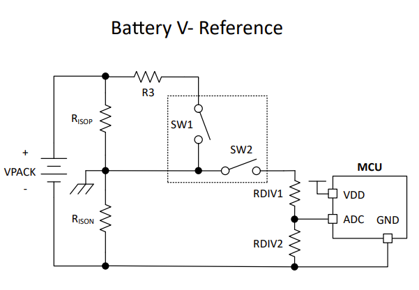
Thank you very much,
Colin.

  • Hello Colin,

    Thank you for reaching out to our team's E2E and for sharing the schematic for your Insulation monitoring application with TPSI2072-Q1.

    Our team is reviewing your request and will be in touch on the next business day.

    Thank you again for your patience as we help review.

    Best regards,

  • Hello Hussain,

    Thank you very much for your help, I look forward to your explanation.

    Have a lovely day,
    Colin.

  • Hello Collin,

    Thank you for your patience and reaching out with this insulation impedance detection circuit with TPSI2072-Q1.

     In the diagram you showed, RsioP and RsioN represent the health of the physical insulation on the HV battery in the system. When the Physical Insulation of the HV battery is healthy (undamaged),  RsioP and RsioN will be in the Mohm range. When the Physical Insulation of the HV battery is damaged, RsioP and RsioN will be in the Kohm range. Therefore, measuring the values if RsioP and RsioN allows us to check or guarantee that the Physical Insulation of the HV battery is undamaged. R3 and Rdiv1/Rdiv2 are selected based on accuracy and High Potential testing considerations in the above architecture. 

    → If you would like to understand the detailed operation of the circuit above, you may find the following design guide useful. If there are further questions, please feel free to reach out here. 

    → The team will continue looking into this and provide a follow-up later this week for recommending precise values. 

  • Hello Hussain,

    Thank you for your explanation.

    I am familiar with the concept of Insulation resistance monitoring, thank you for the design guide.

    I look forward to your team's follow up next week, as this is mainly what I am interested in.

    Have a lovely day,
    Colin.

  • Hello Colin,

    Page 26 of the design guide shows that the measured accuracy is best when the resistors (%0.1 precision) are selected to be close in value to the warning/fault resistance range of the isolation resistors [warning (500 Ω / V d.c. - 2mA); and fault (100 Ω / V d.c. - 10 mA)]:

    Please let us know if there are further questions and thank you again for your patience.

    Best regard,

    Hussain