TPS2553: Current Limiting Lower than Expected

Part Number: TPS2553

Tool/software:

Hi,

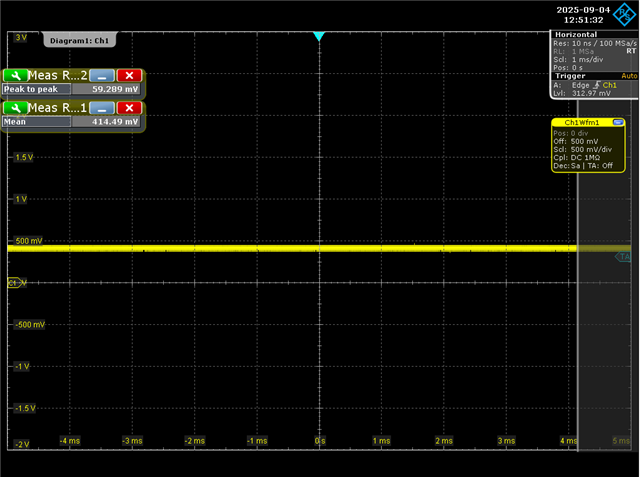
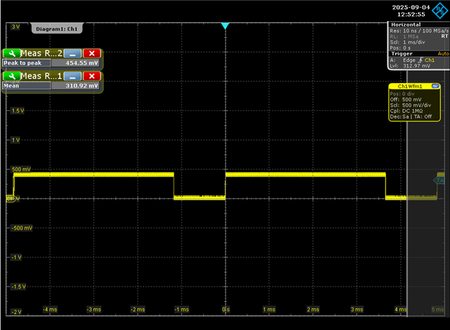
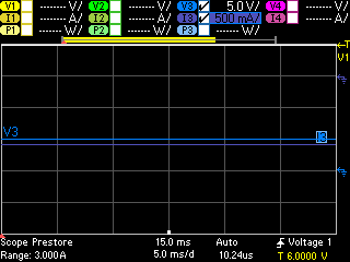
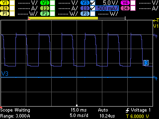
I am using the TPS2553DRV as a current limiter being driven from a 5V/3A DC/DC converter in one of my designs. The ILIM resistor is set to 23.7k, which puts the limiting current at approximately 1.1A. When I pull enough current through the device to trigger current limiting, the output voltage of the TPS2553 drops to ~0V (which is as expected), but the output current drops to ~500mA to ~700mA instead of the current-limiting value set by ILIM. Additionally, the output current is not stable, and jumps around within the 500mA to 700mA range. 

Do you know what might be causing this behavior, and why the TPS2553 is not limiting at the expected 1.1A value?

Thanks,

Adam

  • Hi Adam,

    Can you provide a scope shot?  Additionally, what are you using to pull current?  When I use an e-load, sometimes the two control loops interfere with each other.

    Finally, how have you routed the ILIM resistor relative to TPS2553?  The path from ILIM to RILIM to GND needs to be kept short to ensure accuracy.

    Regards,
    Eric

  • Hi Eric,

    Below is a scope shot of the ILIM pin before the 1.1A current limit is hit, which seems correct:

    After drawing more than 1.1A and hitting constant current mode, I see the current oscillation down to 500mA-700mA and a corresponding oscillating signal on the ILIM pin:

    I have used both an E-load and a pure resistance to draw current, and both result in the same behavior.

    The trace from the ILIM pin to the 23.7k resistor is short, ~0.4mm. The routing from the 23.7k resistor GND to the TPS2553 GND is a little longer, ~3.5mm, due to dense layout. Would this oscillation be the result of a long path between ILIM and GND, even though the current limit seems to be occurring at roughly the correct 1.1A?

  • Hi Adam,

    Sorry, I should have been more clear.  Can you show a scopeshot of the output current?

    The ILIM pin will show DC voltage for normal operation.  I'm not entirely certain why we would see these 1ms dropouts on ILIM.  The routing should be okay as you described it.

    Regards,
    Eric

  • Here is the current into my CC load right before the TPS2553 goes into constant current (~ -1A):

    As is shown, the output voltage at the load is ~5V. 

    Here is the current into my CC load once the TPS2553 goes into constant current:

    Output voltage drops to ~0V (as expected), and the current has the oscillatory behavior.

  • The oscillation is usually due to thermal shutdown.  The device limits current until the die reaches thermal shutdown and the switch completely opens.  Once the die cools down, the switch will re-enable and the cycle repeats.

    I don't see an issue with the current limit level.  Am I misreading the plot? I3 appears to go to -1.1A during the current limiting phase of the cycle.

    Regards,
    Eric