TPS61178: Time from EN going high to output turning on

Part Number: TPS61178
Other Parts Discussed in Thread: LMZM33606

Tool/software:

Hi,

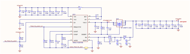
We are using the TPS611781RNWR in our design as per the below schematic snippet to generate 18V from a 12V rail. The EN is controlled from a GPIO. We have seen that there is a quite long delay from the EN going high to the TPS611781 starting up - about 90ms per the below measurement. 

Is the EN -> startup time a constant and known number? I could not see it in the datasheet.

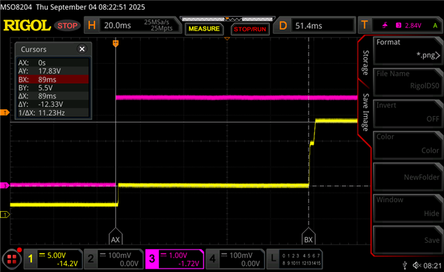
EN -> Output Measurement

Yellow trace (Ch1) is VCCp18V0 rail (output of TPS61178).

Pink trace (Ch3) is EN signal

The VCCp18V0 rail sits at about 2V when EN is low. When EN goes high, the VCCp18V0 rail goes to an intermediate 5.5V level. 89ms after the EN signal goes high, the TPS611781 appears to begin it's proper startup, which takes ~3ms to complete. The VCCp18V0 rail then reaches 18V.

Schematic

  • Hi Jordan,

    82ms startup time looks like not make sense for TPS61178, please refer to the section 8.3.3 Startup for start-up scheme and Figure 28. Startup by EN for startup waveforms on our bench. Usually it should be around ~5ms.

    Can you also measure the VIN and 18v0_bus (VOUT before the Q19) waveforms?

    Regards,

    Nathan

  • Thanks Nathan,

    We did test the measurement you suggested, but I will need to track down the images.

    After some more investigations we believe the 90ms delay may be a single hiccup period - we wonder if the inrush current is triggering a hiccup that after 90ms retries and is then successful. 

    Is there anything we should change to slow down the startup current? I didn't mention, but this 18V supply powers two downstream power supplies (both LMZM33606's) - a P14V5 and N14V5 rail. 

  • Hi Jordan,

    The 90ms does make sense as hiccup time.

    I think the inrush is caused by the output capacitor before the load disconnect FET is much smaller than the capacitor after it.

    It is discussed on datasheet that COUT2 should be no larger than 10 x COUT1 to avoid the inrush current when turning on the disconnect FET.

    Also I think maybe adding some turn on delay on LMZM device EN signal could reduce the inrush current also, but not sure how helpful it is and need a test to verify.

    Regards,

    Nathan

  • Thanks - we do already delay the LMZM enable by 200ms from the TPS61178 enable, but we still see the first hiccup on the TPS61178 enable. There is nothing else on that rail besides the two LMZMs I mentioned that start of disabled, and I suppose all the input capacitors.

    Could something like what is described on page 4 in this app note (SLVA940A) be what we need?

  • Hi Jordan,

    Sure, the point on this AN is to increase the junction capacitance to slow the load disconnection FET turning on, of course it can also help on the inrush current, so also suggest to leave a place holder for potential use.

    But please make sure the maximum gate capacitance and the series resistor is within the expression of formular 5~7 in the AN, otherwise the output voltage will be out of control as the FB pin voltage comes from VOUT2 as also discussed on the application note. 

    Regards,

    Nathan