UCC28251: Use of the I.C. for Full Bridge Application

Part Number: UCC28251
Other Parts Discussed in Thread: LM25037-Q1, LM25037, UCC25600

Tool/software:

Hello;

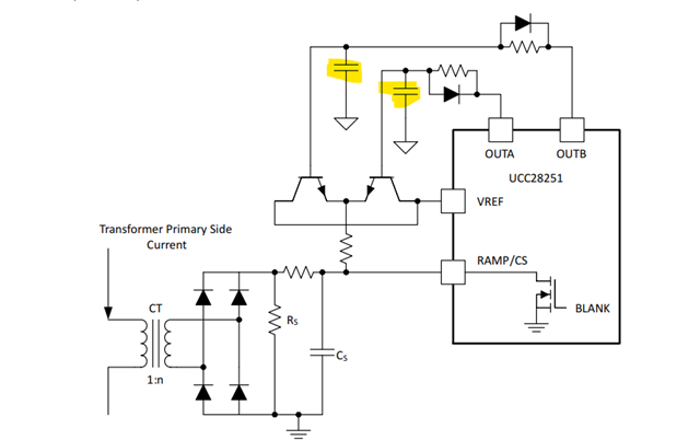
        I am thinking of using UCC28251 for a full bridge rectifier . It will be hard switching converter as most of the Time output power will be around 50W or less. Below are specifications of the DC/DC Converter:

Input Voltage: 600V-700V

Output Voltage: 60V

Output Power :0W-300W

As output power can be low (50W) hence the Primary current of transformer will be low as Input Voltage is High ( 600V -700V) . This low primary current might not be good enough to guarantee soft switching and hence I am going for Hard switching. Will be connecting switching FET's to a external heat sink . Please let me know if the I.C. is suitable for above application or you suggest any other I.C.. Also I will be using gate Driver I.C's to drive the High side and Low side MOSFTS .Thanks. 

  • Also I have one more Query. This is regarding use of the Peak current Mode Control. I shall be using sense Resistor for current sensing. This sensing Output will be given to Both the I lim pin and CS Pin. For ILim  max allowed Voltage is 0.5V and for CS pin  it is recommended to be  3V. Hence I see that I cannot give same signal to both the Pins. I need to add some slope compensation on Current Feedback to make it around 3V . Hence I was think of add a a network as given for LM25037-Q1. Please find the screenshot below:Can I use the scheme mentioned in LM25037 datasheet for UCC28251 as well?

    If I cannot use above mentioned scheme for UCC28251 then I have one query .In the datasheet of UCC28251 they have recommended to used bellow Circuit for Slope compensation. I wanted to know what is the use of the capacitors which I have highlighted in Yellow: Please tell me if my understanding is correct. Transistors driven by OutA and OutB are used as a switch such as when any one of the output is High the switch Turns On and Provide additional charging current for Cs thus increasing the Ramp Slope..

    Thanks in Advance.

  • Hi,

    It looks your input voltage range is narrow, 600V to 700V, then LLC half-bridge resonant converter would be a good choice. The control device can be UCC25600 which can help ZVS all the time.

    LM25037 has RAMP and CS separated but UCC28251 these two are actually 1 pin so not able to generate a slope when the two pins are merged into one.

    For the capacitors highlighted, the voltage on the capacitors is linear rising, the bipolar transistors are in voltage follower configuration so their emitter voltages are following the capacitors voltage. Since the capacitors voltages are rising as a slope the emitters voltage also rising as a slope which create a slope current through the resistor on emitters. So the slope compensation current is generated.

  • Thanks for your reply. I have couple of doubts:

    1> Is CS pin in LM25037 and Ilim Pin in UCC28251 have same functionality? As I can see in datasheet Both Pins are used for over current Protection.

    Also RAmp Pin in LM25037 and Ramp/CS in UCC28251 are same .

    If my understanding as mentioned is correct then I wanted to Know if I can use same circuit at Ramp/CS pin in UCC28251  as shown in Ramp pin in LM25037.

    In case of using the circuit on Ramp as mentioned in UCC28251 datasheet , if I use the 2 transistors as switch and then through a resistor Charge the capacitor at Ramp/CS pin (Cs) with a current limiting resistor between the Vref and Capacitor (Cs) then will that circuit also work. Please let me know.

    Thanks in Advance.

  • Hi,

    UCC28251 Ilim pin is not for peak current mode control and only for current limit so its threshold is not controlled by feedback loop. So it is not CS pin like in LM25037. That’s why UCC28251 needs to add slope compensation as show and you cannot use LM25037 slope approach for UCC28251.

    I am not understanding your description how you want to do the slope for ucc28251. Please draw a circuit to show so to help check if ok.

  • Hello;

           In the Datasheet of LM25037 , CS pin description is given as follows:

    So I do not understand why CS of LM25037 is not same as ILim pin in UCC28251. Both pin have the functionality of Providing peak current limit. Please explain me what is the difference between CS in in LM25037 and ILim pin in UCC28251.  

  • Hi,

    LM25037 has internal mechanism to do peak current mode control so ok to do its datasheet suggested.

    UCC28251 dos not have peak current mode control so its slope compensation needs to follow its datasheet suggested. 

    These are what we know and are our recommendations. If you want discover then you can try but based on what we know you can only follow the datasheet to get work.

  • Hi,

    To be more specific, UCC28251 has to CS for peak current mode control and cannot use ILIM. But CS is its RAMP so these two pins are combined. ILIM cannot be used in UCC28251 for peak current mode control. These make UCC28251 different from LM25037.

    LM25037 RAMP is separated from CS and CS is for its peak current mode control so you can use RAMP to produce slope but in UCC28251 CS is RAMP and CS is for peak current control, ILIM cannot do peak current mode control.

    That is why the slope circuit is invented for UCC28252 and cannot use the one from LM25037.