Tool/software:
Dear
I have several questions about BQ25751 charging circuit.
First:
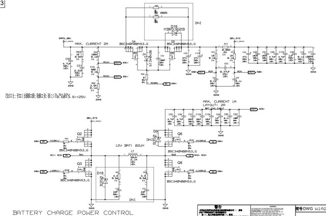
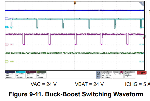
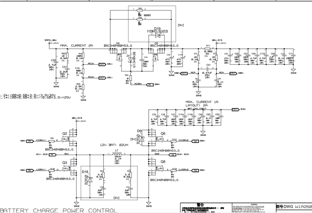
My circuit is designed 30V power input, 26.4V float voltage for 24V lead acid battery charging, max charging current is 1A. Switching frequency is 300KHz.
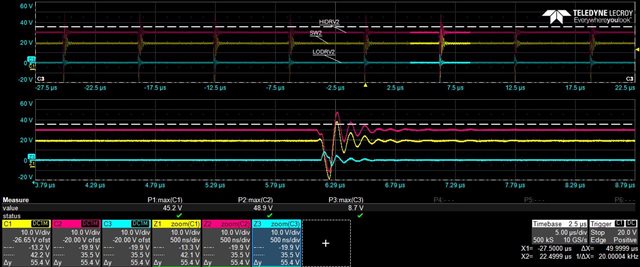
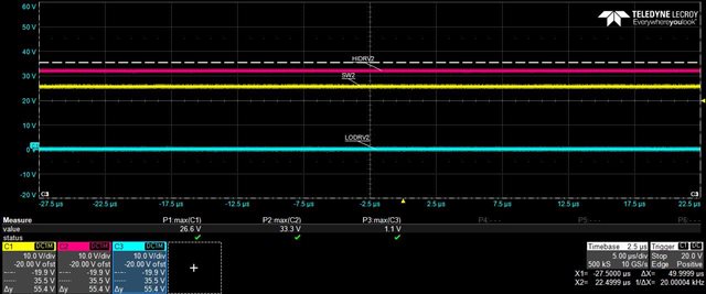
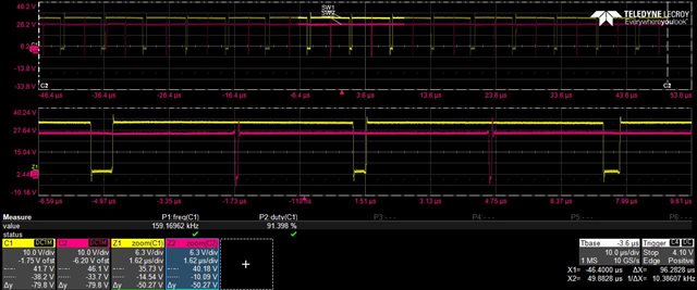
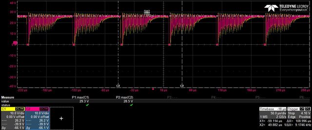
When I  adjust the input voltage as 28V, the frequency is 150KHz.
Could you please help answer why the frequency changed?
Second:
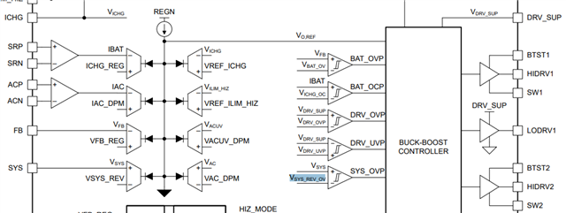
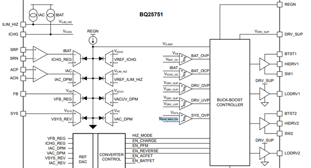
About the UV/OV function, from the datasheet, I find if the input voltage is over voltage or under voltage, the chip will close the ACFET by the pin ACDRV.
From the functional block diagram, I find if the ACFET is short, the OV/UV function is also active, and the chip will close the buck-boost controller, right?
Third:
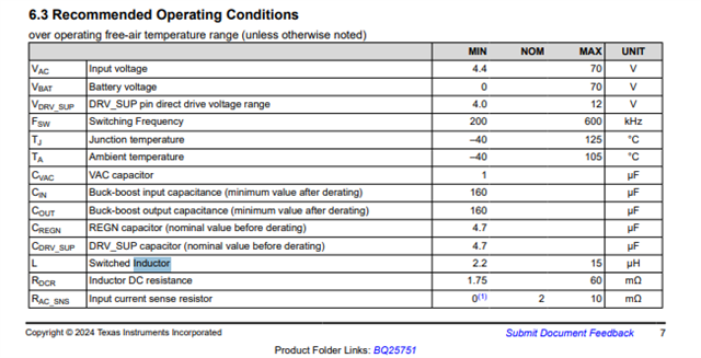
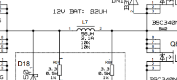
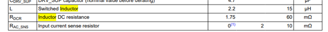
For the inductor selection, datasheet recommends inductor is 2.2~15uH, DCR is 1.75~60mohm. Is it necessary to select inductor per this? Or I can select inductor according to buck circuit caculation?
 Hope I can receive your reply soon.
Thanks so much.