Tool/software:
Hello,
I think there is a problem with my design method. Please give me some advice.
[About the assignment]
We are considering using the TLVH431AQDCKR for output control of a flyback converter.
The circuit configuration and implementation values are as shown below.
The REF voltage of the TLVH431 is malfunctioning and clamped at about 0.5V during the output rise. The correct REF voltage is 1.24V.
This causes the output voltage, which should be 12V, to be clamped at around 5V and remain stagnant, not rising.
[Advice Request]
1 : What causes malfunctions like waveform ① of the TLVH431 in this circuit configuration?
2 : Please give me some advice on how to solve the malfunction.
3 : Not limited to this configuration, if you know of any cases where the REF voltage of the TLVH431 clamped at an incorrect value, please tell me the conditions under which this occurs.
[Circuit & Wavefrom]
・Circuit
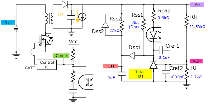
A secondary side soft start circuit (Rss2, Dss1, Css) is configured for startup control.
Although it is omitted in the circuit diagram, a primary side soft start circuit is also implemented.
The aim is to gradually raise Vo by switching to a primary soft start, a secondary soft start, and finally to output control using a shunt regulator.
・Waveform
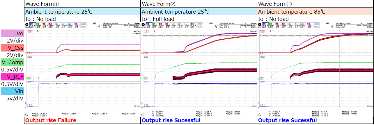
Waveform ① is from when the device malfunctioned, and I would like to solve this. The waveform is No load and at room temperature.
*The cathode current is calculated to be at least 0.33mA, which is sufficient.
Ik = (Vo - V_Css - Vf_Opt - Vf_Dss1 ) / Rcap = (5 - 2 - 1.2 - 0.5) /3900 = 0.33mA > Ikmin 0.1mA
Waveform ② is at full load, and waveform ③ is at high temperature, and both are successful startup even with the same implementation values.
Best regards.