TPS2373: Use the TPS2373 in a dual-signature PD system

Part Number: TPS2373
Other Parts Discussed in Thread: TPS23881, TPS2372

Tool/software:

Dear Madam/Sir,

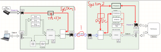
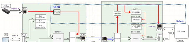
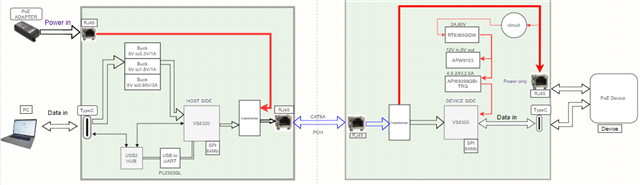
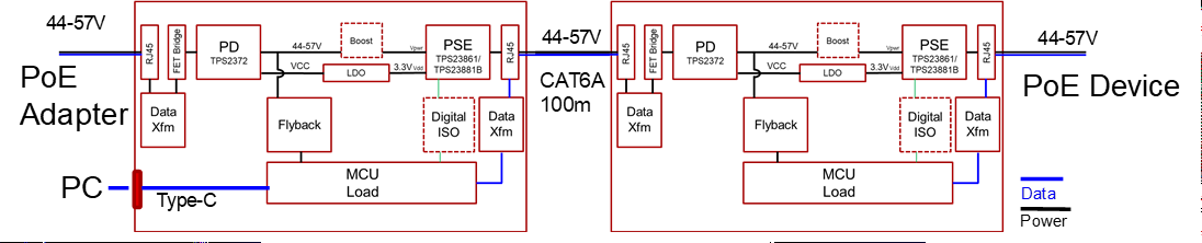
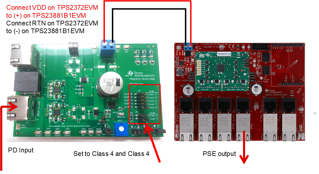
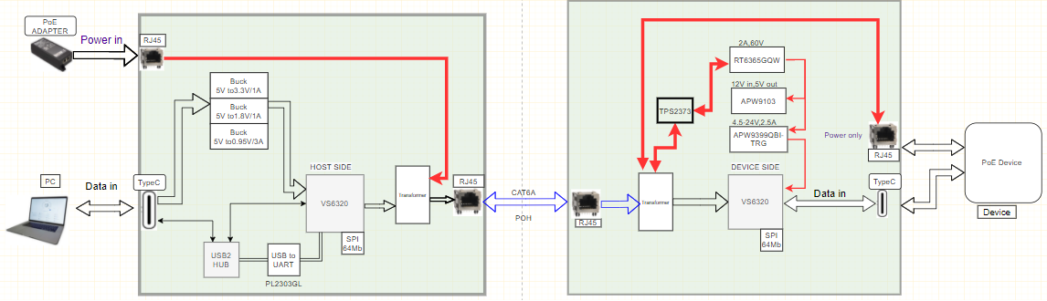
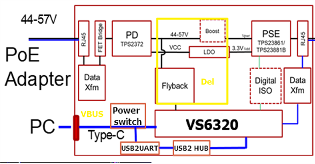
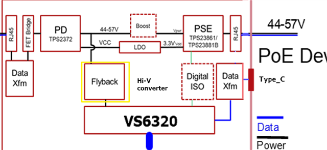
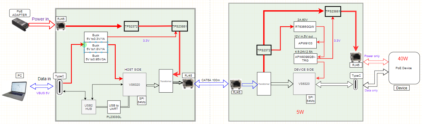
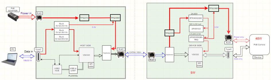
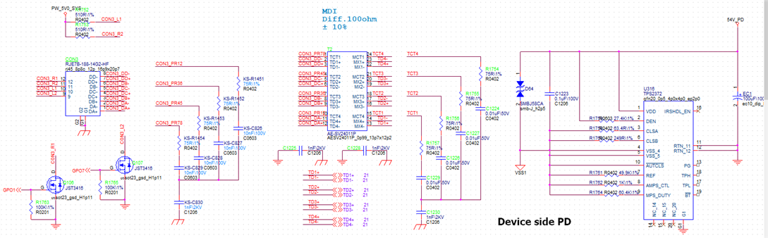
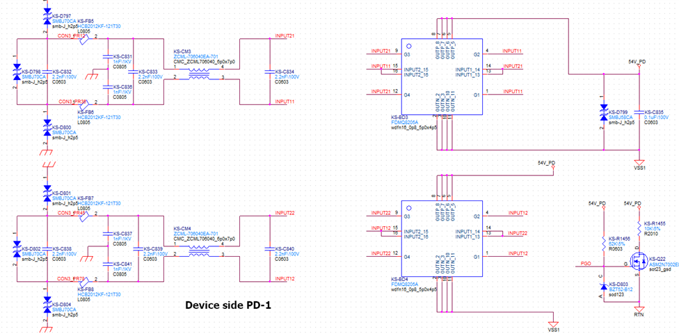
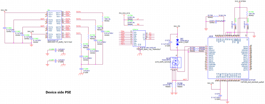
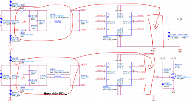
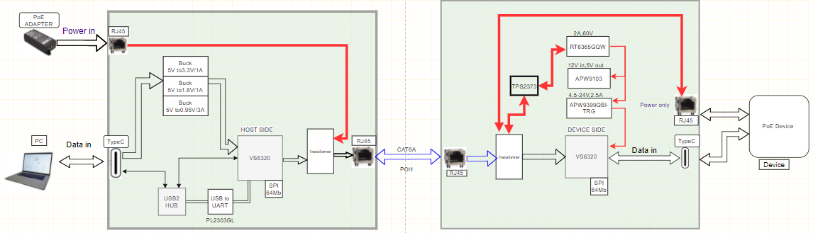
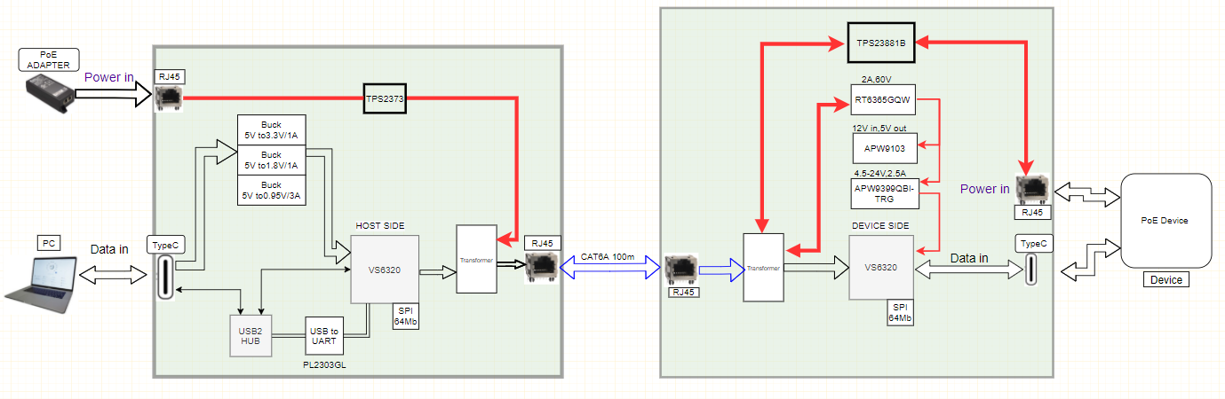
We'd like to build a system as follows.

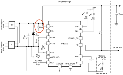
We have never used the dual-signature PD before, so we are not sure whether this architecture is workable or not.

Please give us some suggestions to complete this design.


By the way, the customer provided an idea as follows:

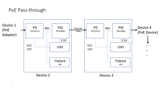
They want to use a PoE adapter to provide power to the endpoint PoE camera.

PoE adapter → PD (pass-through) → PSE → PoE camera

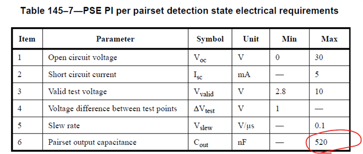
We think the PoE signature detection may fail.

Is the customer's idea workable or not?

thanks

  • Hi Charles,

    Thanks for reaching out.

    According to the system diagram you have provided, we have come up with two possible options as following:

    Option 1:


    Diagram: 

    We assume system 1 power is supply by the buck converters connected from type C port. Only PD through required with TPS2372. System 2 will have a PSE TPS23881. A dc/dc will be needed to regulate the voltage. This will need minimum parts to do PoE PD for system 2 and PoE device. The PoE signature will still work. But the CAT cable between system 1 and system 2 cannot be too long (especially not for 100m here), since the system might fail Sifos test with long cables. The CAT cable between system 1 and system 2 will have 57V as long as PoE PD is established on TPS2372, which will be a ESD or Inrush current concern for frequent plug and unplug.

    Option 2:

    This is a PoE Daisy-Chaining solution which has been used before as following:

    Using one PD and one PSE in each system, it will be able to do PD for each system in the chain. And it can be extended even further.

    The 802.3 compliance and distances between devices will not be a concern comparing to option 1.

    Please let me know if you have any questions about these two options.

    Best regards,

    Zhining