TPS61033: unstable quiescent current with no load

Part Number: TPS61033

Tool/software:

After assembly, we have our boards tested for functionality. This involves measuring the current consumption of the TPS61033 component with and without load.

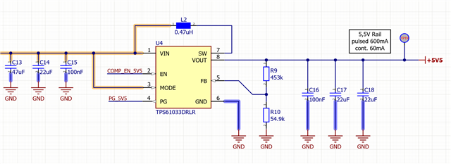
  • The voltage supply is 3.3V
  • The output voltage is set to 5.5V
  • The mode pin is permanently pulled to VCC and therefore according to the data sheet in forced PWM mode
  • and the enable Pin is switched by the flying probe adapter

At the moment we have produced arround 1000 boards. 90% of this PCBs have the same results, when the devices are enabled and no load is applied: arround 35mA.
We were expacting this result, due to information in the datasheet, that the efficiency at light loads is below 1% 

10% of these board have a completely different current consumption of only 800µA.

We have also tested a small sample manually, but the results were the same.

Do you have any known issues with the mode pin, because we believe that this might be the problem, that the forced PWM mode is not allways activated?

Thank you very much!

Regards,
Lukas

  • Hi Lukas,

    Where does VCC come from, do you have a schematic for this application? 35mA should be normal for your application, because you choose FPWM mode, it will keep frequency even under no load condition. So its efficiency under light load or no load will not good.

    If you care about this efficiency, may be you need to choose auto PFM mode. Pls connect this MODE pin to GND. Thanks.

    Aurora

  • Hi Aurora,

    the board is supplied from an external DC power supply with the mentioned voltage from above (3.3V)

    Due to our company restrictions i can only provide you a snippet of our schematic.
    Our problem is not the efficiency. Our main problem is, that 10% of the whole produced boards have a completely different current consumptions.

    As mentioned above the main problem ist that we are expecting that every board should run in the forced pwm mode. But it seems that 10% run in the auto FPWM mode?

    This makes us uncertain whether we can install these assemblies without concerns.

    regards,

    Lukas

  • Hi Lukas,

    Can you give me some test waveforms of the wrong board? I want to see the start-up waveform include Vin, Vout, SW and MODE. Looking forward to your reply. Thanks.

    Aurora