LM5164-Q1: Odd current behavior with LM5158-Q1

Part Number: LM5164-Q1
Other Parts Discussed in Thread: LM5158-Q1, , LM5158, LM5164, LM65645-Q1

Tool/software:

Hello,

We are having an issue with the LM5164-Q1 and the LM5158-Q1.

We are using a LM5158-Q1 to generate a 45V from our 28V power supply input and then a LM5164-Q1 to generate a 5V and another to generate a 15V.

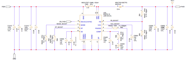
Our 45V schematic @ 350mA max.:

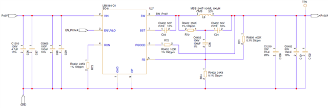
Our 15V schematic @ 525mA max.:

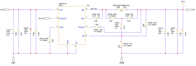
Our 5V schematic @ 650mA max. (GNDM is connected to GND at a single point somewhere else in our schematic):

On the board, the load is not the max. one as we did a prototype only with the power supplies and few other functions.

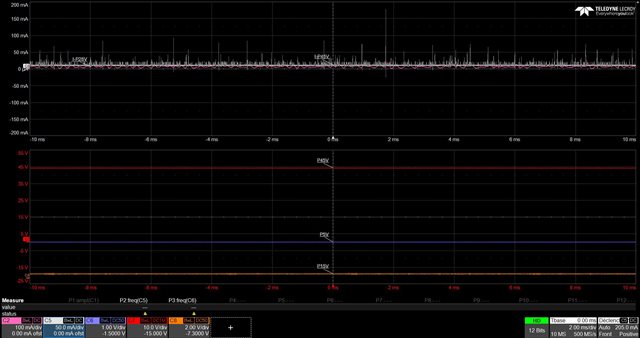
28V on / All others off:

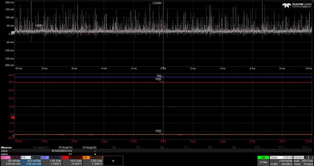
28V & 45V on / All others off:

28V & 45V & 5V on / All others off:

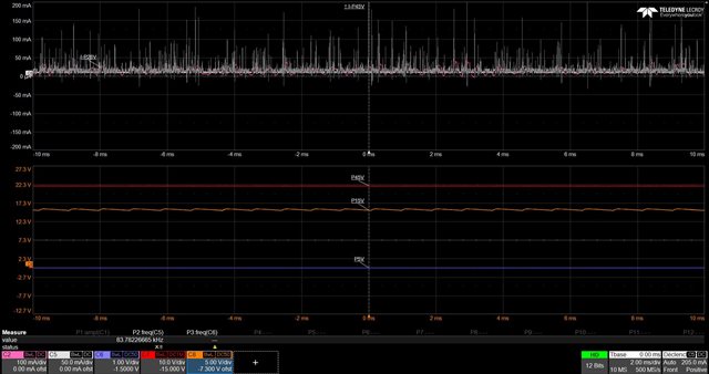
28V & 45V & 15V on / All others off:

All on:

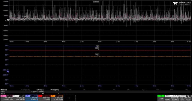
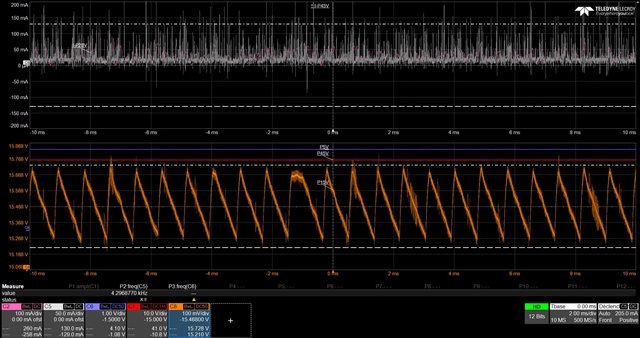
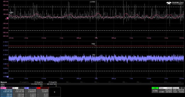
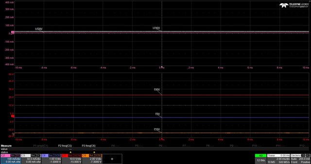
As you can see, as soon as a 5V or 15V is activated we do see an odd behavior on the 45V current (white curve) and 28V current (pink curve).

Considering there is not so much load on those converter outputs, we don't understand this behavior.

As you can see there is not so much ripple on the converters output.

Note that we tried adding additional capacitors on the 5V and 15V DC/DC input (100nF x 2 + 4.7µF) without change.

Any idea ?

Out of interest, a 1.2mF bulk capacitor is present on the 45V to act as a power backup in case of 28V power supply loss.

Best regards,

Clément

  • Hello Clement,

    What is the white curve?  VOUT?

    If its VOUT, its expected, you are drawing currents at random intervals and you are seeing frequency components of the downstream converters interacting with each other and with the upstream converter (LM5158).  if this is undesirable, then you will need filters to isolate the disturbances.

    Hope this helps,

    David.,

  • Hello,

    The curves legend:

    • Pink curve: current on 28V
    • White curve : current on 45V
    • Red curve: voltage on 45V
    • Purple curve: voltage on 5V
    • Orange curve: voltage on 15V

    The LM5158-Q1 generates the 45V.

    It could be the frequency components of the downstream converters (the LM5164 parts that generates the 5V and 15V), but the current value seems a bit high (200mA with some spikes above 1A), no ? Also, the downstream loads after the downstream converters are static so we wouldn't expect such variations.

    There are other converters on the 45V which are not leading to such behavior.

    Clément

  • Hello Clement,

    how are you measuring the current?  the inputs current to a buck is transpoixalt whos center points are at IOUT.  if you have an input filter to the buck and measure quete side of input filter, then you will masure DC current.  if you do not have an input filter on the inputs of your bucks, the currents will have peaks, and how much peak you will have will dempend on the ioimpedence.  what is the concern with the currents you are seeing?

    Thanks.

    David.

  • Hello David,

    I have a hard time understanding your message

    We are measuring the current with a current probe on the boost output.

    As you can see from the schematics from the first post, we don't have an input filter on the bucks (no specific inductor).

    Our concern is that the current value is quite high considering there is almost no load on the bucks output nor load change during the measurements and we even observe peaks above 1amp.

    We only see this behavior when LM5164-Q1 bucks are ON, we don't when other bucks (e.g. LM65645-Q1) are ON.

    Does it mean that the LM5164-Q1 has specificities that would require implementing the input filters you were suggesting ?

    We never encountered such issue in the past with TI bucks.

    Best regards,

    Clément

  • David,

    We tried adding an inductor on the buck input to filter but it had no effect on the observed current.

    Could it be related to our design of the LM5158-Q1 boost from the first post ?

    We designed it for an input voltage between 18V and 32V and an output of 45V at 225mA nominal / 350mA maximum.

    Best regards,

    Clément