Other Parts Discussed in Thread: LM25143
Tool/software:
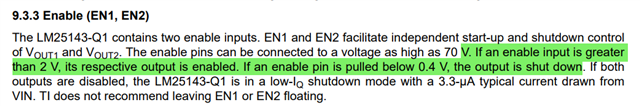
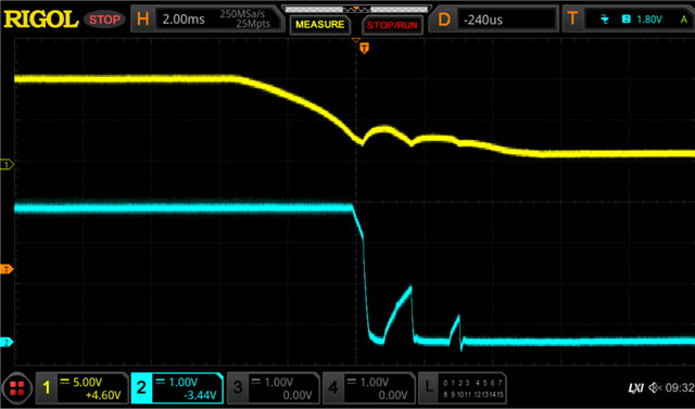
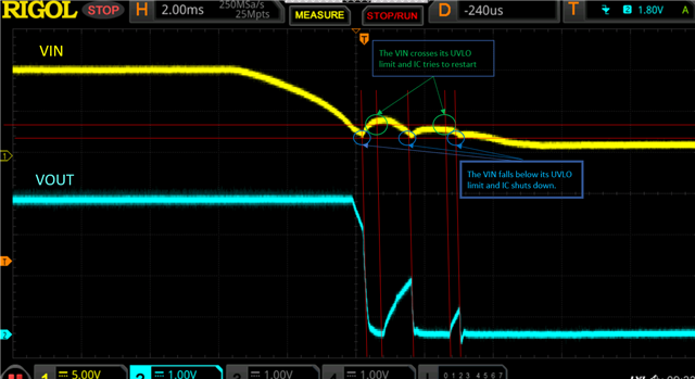
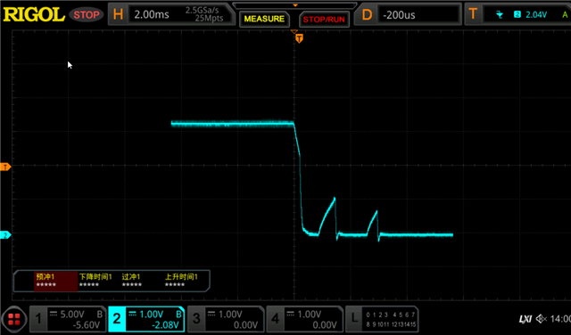
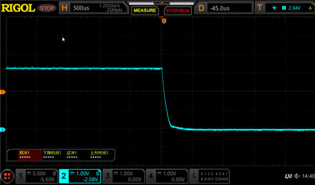
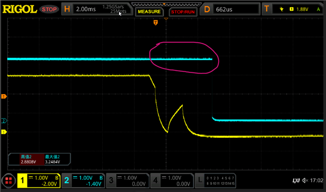
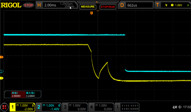
The load is 20A. After the power is cut off, the output drops and then rises sharply. What is going on?CH1 is the output and CH2 is the enable pin.
Tool/software:
The load is 20A. After the power is cut off, the output drops and then rises sharply. What is going on?CH1 is the output and CH2 is the enable pin.