TPSM33615: VCC Pin Under 3V

Part Number: TPSM33615
Other Parts Discussed in Thread: LM66200

Tool/software:

Hello,

I am working on an application with the TPSM33615 and I am seeing behavior where VCC remains under 3V (only rises to ~1.9V). My schematic is configured for a 5V output, but I only see 1.4V on the output rail.

  • Vin: 24V
  • Mode Select: GND
  • Chip: TPSM33615FRNDN

So far I have: 

  • checked for shorts from vcc to ground 
  • confirmed my feedback resistor values match the schematics (measured the feedback pin at ~0.2V)
  • attempted to remove the 1uF cap on VCC. 
  • dropped VIN to 12V.

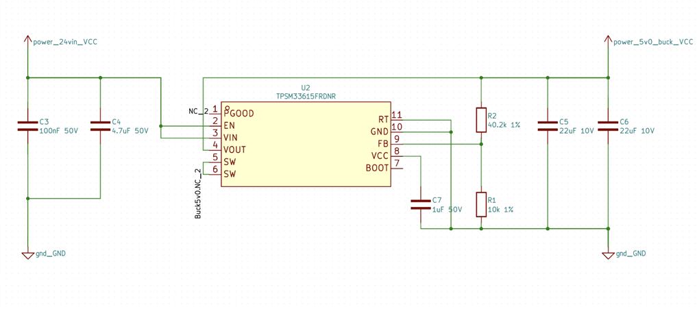
My schematic is attached. 

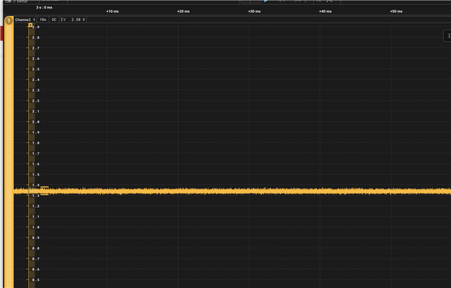
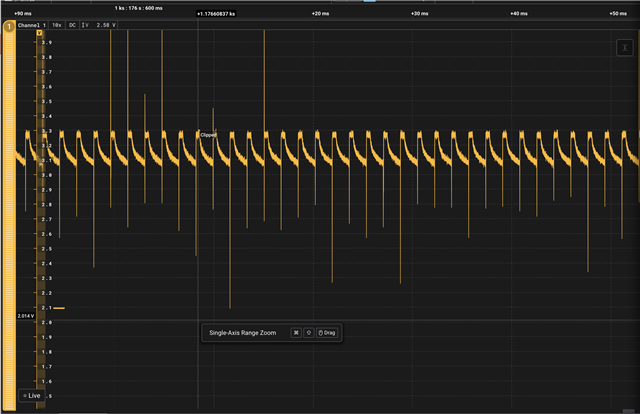
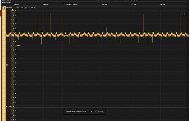
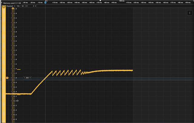
Scope capture of VCC (pin 8) on power on: 
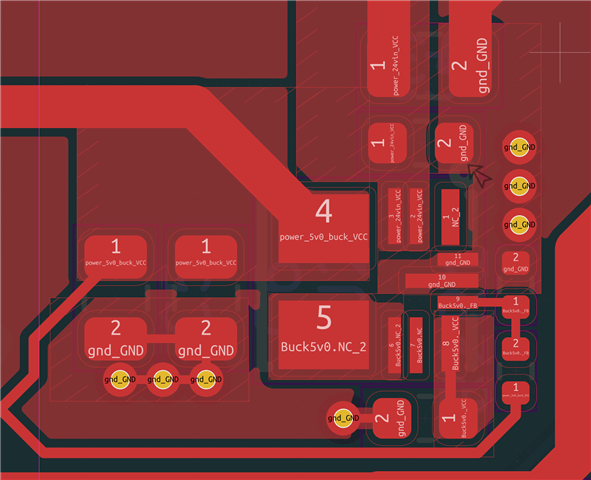
Layout: 

I would appreciate any recommendations for next debugging steps!

Thanks,

-AK

  • Hi,

    I have received your query. Let me look into, I will get back to you soon.

    Thanks,

    Pramanik Patel

  • Hi,

    Schematic seems of to me.
    Can you please check the following things:

    1. Check the EN pin voltage after VIN is applied, is it above UVLO (Sometimes there is a soldering issue and EN may not get sufficient voltage to turn the device on.
    2. Can you please replace this device with a New one and see if the issue still exists.

    Thanks,

    Pramanik Patel

  • Thanks for the response. EN pin voltage looks good. Oddly I see this additional behavior.

    • The output power of this buck goes into VIN1 pin of LM66200.
    • The VIN2 pin of the LM66200 has USB 5V power
    • When I just power the board from 24V (buck only), the output is 1.4V and it doesn't seem to be switching. 
    • When I power the board with USB and 24V input to the buck (the Buck goes unloaded as the mux selects usb power), I see the VCC voltage rise to 3.3V, and the output of the buck goes to 2.4V. (it seems to turn on, to the wrong voltage)
    • After the output of the buck goes to 2.4V, I can un-power the USB and the buck remains at 2.4/vcc remains at 3.3
    • The FB pin at this time is 0.5V, and the regulator never hits 5V. 

    The power draw of my system is ~0.25W

    I have some new parts on order, curious if you have any more thoughts on what could be going on.

    Thanks!

  • Hi Anand,

    Thanks for explaining the problem in detail. I have a test plan in mind, 

    1. We will try to test only buck. Can you please just unload the buck (disconnect LM66200) ?
    2. Can you gradually increase Vin from 0 to 24V ? But while Vin is just approaching 0.7V, can you please check if Vcc is rising to 3.3V?


             3. If we see Vcc rising to 3.3V then the LDO inside is working good.

             4. Now we can gradually increase the VIn above 1.23V and see if the buck starts to regulate at no load.

             5. Also during the above step, you can monitor the FB pin and see if it is at 1V.

    The whole idea of the above test sequence is to ensure that startup sequence is proper. Let me know if have some further questions.

    Thanks,

    Pramanik Patel

  • Thank you for the detailed response! Replacing the chip solved the issue. I suspect it was a poor solder connection like you mentioned initially. 

    Best,

    Anand

  • Hi,

    I am glad that I was able to help you. Let me know if you need further assistance.

    Thanks,

    Pramanik Patel