LM25143-Q1: Ringing phenomenon

Part Number: LM25143-Q1

Tool/software:

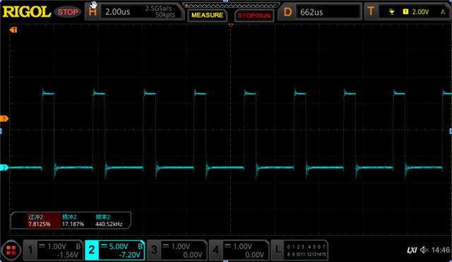
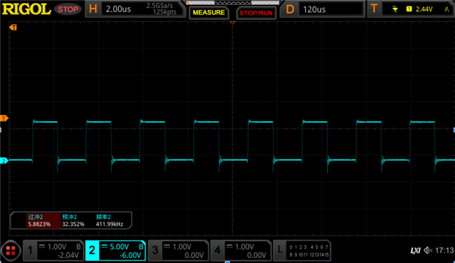
When the load is 30A, there is a large ringing phenomenon when measuring the SW pin (as shown in Figure 1). When the load jumps from 0A to 20A, there is a large ripple at the output (as shown in Figure 2). Please help me analyze where the problem is. Thank you.


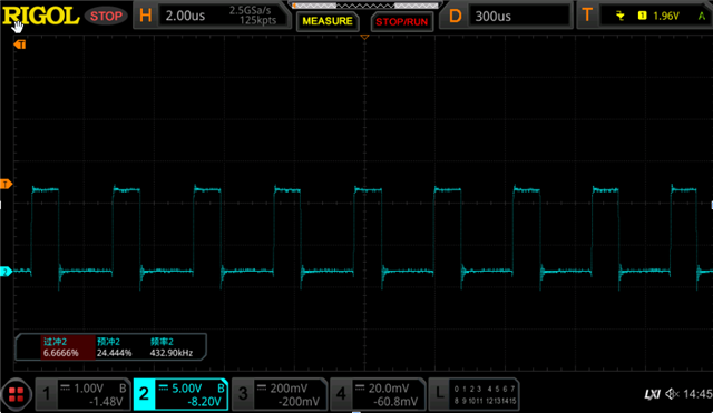
Figure1:CH2 is the SW pin

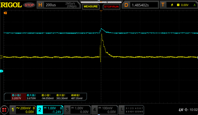
FIgure2:CH1 is the Ripple voltage in AC mode and CH2 is the output voltage in DC mode

  • Hello Peigen

    Could please check if your probe is inverted or oscilloscope sets up probe in invert mode? Additionally, share your schematic for review.

    Thank you 

    Regards

    Onkar Bhakare

  • Hi Onkar,

    The probe and the oscilloscope is ok,and have you not seen this phenomenon before? Is there any way to improve it?

  • And I have other test pictures about this test in SW pin:

  • Hello Peigen,

    During a load transient from 0 to 20A, a temporary voltage drop (undershoot) is expected as the converter adjusts to the new load. While an overshoot can occur, it’s unlikely to happen in isolation. Typically, the output will undershoot initially, and then potentially overshoot as the control loop corrects the voltage. An overshoot without a preceding undershoot is not a typical behavior. 

    May I request your schematic for review? Additionally, could you please brief on how experiment is being conducted?

    To see how converter is reacting, comp node waveform capture simultaneously with output voltage would help here

    Thank you

    Regards

    Onkar Bhakare 

  • Hi Onkar,

    Thank you for your reply. I actually have two questions. The first is that when the load is 30A, I see significant ringing on the SW pin waveform, as shown in Figure 1. Is this significant ringing normal? Are there any improvements?

    The second question is that when measuring load transitions, I get the waveform shown in Figure 2. I used an electronic load as the load device, performed the load transition, and measured the output waveform, which shows the waveform shown above. This waveform has significant overshoot, which is undesirable. We'd like to ask if you could analyze the issue and whether there are any improvements or solutions. Thank you.

    and the sch is as below:

  • The first is that when the load is 30A, I see significant ringing on the SW pin waveform, as shown in Figure 1. Is this significant ringing normal? Are there any improvements?

    It is bit hard to figure out peak magnitude of ringing from attached waveform could you please share its value.  Use shortest measurement loop technique with full bandwidth.

    Do you have a complete Quickstart for your design. If not, I would highly encourage doing that and share it for review. Here is the link -  LM5143DESIGN-CALC Calculation tool | TI.com

    As mentioned kindly share the comp waveform along with vout to understand the issue better.

    Thank you

    Regards

    Onkar Bhakare