TPS62A04B: The switch frequency goes to much higher during 0.5A-1.2A output current

Part Number: TPS62A04B

Tool/software:

This chip is supposed to have a fixed 2.2MHz switch frequency for medium to heavy load and lower frequency for light load as it works as PFM mode. While in our design, I found the switch frequency can go high to 4.7MHz at a medium light load saying 0.5A output current. 

Is it designed to be like that? Or anything could be wrong with my design? It's a quite simple circuit and we couldn't do much wrong with it. 

  • Hi Paul,

    The device shouldn't switch with that high frequency. Can you share the scope shot, how the waveform looks like and what are the settings in your scope? What kind of load are you using, is it constant current load or a constant resistance load? Also having info about the test conditions will be nice to have like Vin, temperature etc.

    Best Regards,
    Zakir

  • Hi Zakir,

    Thanks for your response. 

    Sure, please find the scope shot at 0.8A current load. The waveform looks quite stable. The settings are no problem as the switch frequency is normal as 2.2MHz when the output current is above 1.2A. 

    The load is electronic constant current load. The input is a onboard 5V DC/DC converter from 12V input to the board. It was tested under room temperature. 

    I also attached the schematics for your information. It doesn't make any difference with Cff on or not. 

  • Hi Paul,

    Are you performing the test on our EVM or on your own layout? Can you re-test with a new device on board and let us know if it happens again. But this time with a constant resistance load, i know constant current would not be a problem here but just wanted to see what is the root cause here. Also, the probe which is being used at the switch node will be an active probe i hope and if not you must verify that you are not overloading the SW node with a 50Ohm termination. In any case, the device is not designed to switch with such higher switching frequency. Would like to know what you saw once you are done.\

    Best Regards,
    Zakir

  • Hi Zakir,

    We are testing on our own layout. And yes, I re-tested with a constant resistance load and active probe. It doesn't change the result. 

    We have 3x5V to 3.3V,  one 5V to 2.5V and one 5V to 1.2V converters with the same TPS62A04B. They are pretty much same circuit and layout except the FB divider resistors value for different outputs voltage. Only the 1.2V has the expected behaviour (PFM with low frequency under 1.2A- output current and around 2.2MHz when the output current higher than 1.2A). For the 3.3V and 2.5V, the switch frequency goes higher than supposed. 

    To make sure it's not the problem with the layout, I changed one of the 3.3V converter to 1.2V by changing the FB resistors. The switch frequency turned out to be correct as expected. So the output voltage matters. Still can't understand why. 

    Thanks,

    Paul

  • Hi Paul,

    Apologies for the delay in my response. Can you try to reduce the divider by one decade for 3.3V Vout like using 10k and 2.2k and then see if you see the same behavior. Finally, can you share your layout with us so that we can further dig into the matter. Thanks Slight smile

    Best Regards,
    Zakir

  • Hi Zakir,

    Tried 10K and 2.2K, it didn't make improvement. 

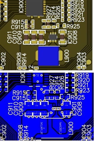
    Please find our layout below for your information. The upper one is 3D and lower one is 2D view. 

    Thansk,

    Paul

  • Hi Paul,

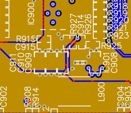
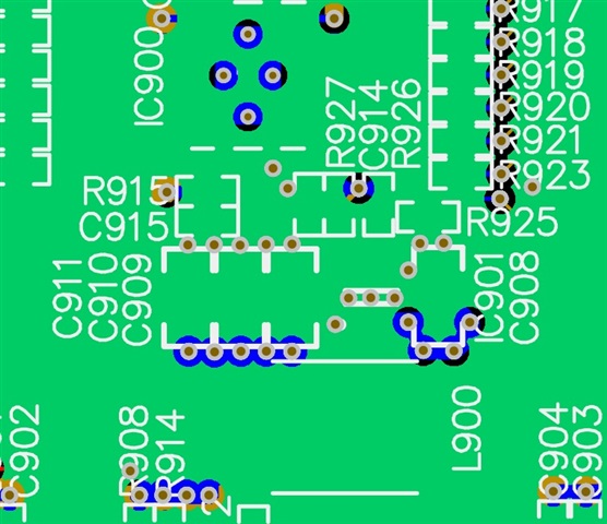
    With the layout almost everything is visible except the Vias or internal signal layers. I want to see the GND of feedback divider and also the trace of VOUT signal that connects the feedback divider. Can you share one more screenshot showing these things? I appreciate for being patient and bearing with us. 

    Best Regards,
    Zakir

  • Also Paul, in the meantime i will try to do the same thing on my side and let you know what i observe. Slight smile

  • Hi Zakir,

    Please find the enclosed pic for the GND and the trace of VOUT and divider.

    Thanks,

    Paul

  • Ground layer

  • Hi Paul,

    Apologies for the confusion earlier. I’ve since learned that a higher switching frequency can happen when using small inductors. During TOFF, the zero-current comparator may trip early, which ends the low-side phase and starts the high-side phase sooner. To keep regulation, the device then switches faster. Because this varies from device to device, the datasheet only lists a typical fsw and no min/max values.

    Thanks for your patience, and sorry again for the back-and-forth.

    Best Regards,
    Zakir

  • Thanks Zakir for the clarification. All good.