LM5123-Q1-DESIGNCALC: Ruvlo_bottom_calc not taking 10uA into account

Part Number: LM5123-Q1-DESIGNCALC

Tool/software:

Hi, in "LM5123 Boost Controller Design Tool" spreadsheet,

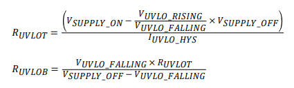
Ruvlo_bottom_calc doesn't seem to be catering for the 10uA hysteresis current.

e..g. with Vuvlo_on=21V, Vuvlo_off=18V, Ruvt 252k. It then shows Ruvb 14k, 

With 21V input, threshold 1.1V and 10uA, it should be around 16k

regards

Kari

  • Hi Kari,

    Thanks for using the e2e forum.
    I compared the equations inside the spreadsheet with the datasheet equations.
    Both account for the 10uA hystersis current.
    The only difference is that the quickstarter switches the supply_on and supply_off times in the calculation, which should not affect the results themselves.

    Datasheet:

    Quickstart calculator:

    R_UVLOT = ((Vsupply_on * (UVLO_falling / UVLO_rising)) - Vsupply_off) / I_uvlo_hys

    R_UVLOB = UVLO_rising * R_UVLOT / (Vsupply_on - UVLO_rising)

    Please let me know fi there are additional questions on this.

    Best regards,
    Niklas

  • Hi Niklas,

    exactly, there's no 10uA in that R_UVLOB calculation.

    from datasheet, "When the UVLO pin voltage falls below VUVLO or during the device configuration time, the current sink is enabled, causing the voltage at the UVLO pin to fall quickly."

    So, in active state the 10uA is turned off and threshold is dropped to 1.075V

    Therefore, before active state, 10uA is enabled and threshold is 1.1V ?

    example, in the spreadsheet i entered 22v and 18.5V >> 300k & 15.789k

    So current required in R_UVLOT to get the voltage above 1.1V..

    i = 1.1/15789 + 10uA = 79.7uA

    79.7uA x 300k + 1.1V = 25V, not 22V

    regards

    Kari

  • Hi Kari,


    The LM5123 has two features at the UVLO pin. One is the voltage hysteresis of 25mV.
    The second is the current sink of 10uA, which is active in the range between Ven and Vuvlo.
    These two features are independent of each other.

    From my understanding, it is sufficient to account for the 10uA in just one of the resistor equations (in this case, the high side resistor).
    So there should be no mistake in the equations.

    Are the thresholds you mention based on calculation, or was this observed on bench testing with a real device?

    Best regards,
    Niklas

  • Hi Niklas,

    This is based on calculation and the spreadsheet. I want to get the values correct before i have prototypes, not afterwards.

    The spreadsheet throws up a high value (250k) for Ruvt_calc and allows a manual entry of Ruvt. So now the bottom resistor Ruvb will need to take the 10us into account and it doesn't.

  • Hi Kari,

    Can you confirm the turn-on/-off values you want to achieve and the resistor values according to your calculation?
    As per your initial thread:
    Vuvlo_on=21V
    Vuvlo_off=18V
    Ruvt  =252kOhm
    Ruvb = 14kOhm or 16kOhm

    As we have LM5123 EVM boards available, I can offer to verify the equations with bench measurements.

    Best regards,
    Niklas

  • Hi Niklas,

    Ruvb can't be both 14k or 16k, there needs to be only one answer. Picking the wrong one would be a 14% difference in target voltage, meaning that it might only just about turn on at 24V.

    The overall problem here is that the spreadsheet formulas are wrong, they're not the same as the datasheet formulas.

    R_UVLOT = ((Vsupply_on * (UVLO_falling / UVLO_rising)) - Vsupply_off) / I_uvlo_hys is essentially scaling Vsupply_on. Well, you can't do that because there's an implied 10uA when Vsupply_on is the target.

    R_UVLOB is much worse. Its using Vsupply_on in the calculation, which would be ok if it also had the 10uA in the equation. But it doesn't. So it would be better if it followed the datasheet formula of using only Vsupply_off, especially as Ruvlot can be manually entered.

    Anyway, I've read in the datasheet that the source resistance for UVLO needs to be around 5k, so i can't have a wide difference between the On and the Off voltages. So now i'm going for 91k for the top resistor and 5k6 for the bottom resistor. Which hopefully should give approx; Von 19.885V and Voff 18.543V

    regards

    Kari

  • Hi Kari,

    I tested on our EVM board with 91kOhm top and 5.6kOhm bottom resistor.
    The test results gave:
    Turn-on: 19.69V
    Turn-off: 18.48V

    This results is within 1% of your calculation.
    I hope this bench test result gives you more confidence for your design.

    Best regards,
    Niklas

  • thank you so much Niklas!