BQ34Z100-G1: Clarification on Learning Cycle Procedure for BQ34Z100-G1

Part Number: BQ34Z100-G1
Other Parts Discussed in Thread: BQ34Z100, BQSTUDIO

Tool/software:

Hello Team,

In our project, we are using the BQ34Z100-G1 fuel gauge and are currently performing the learning cycle by referring to the document:

Application Report SLUA925 – November 2018 – "How to Complete a Successful Learning Cycle for the bq34z100"

We have configured the parameters as per the document:

  • Design Capacity: 2900 mAh

  • Charge Term Taper Current: 290 mA

  • Dsg Current Threshold: Default (60 mA)

  • Chg Current Threshold: Default (75 mA)

  • Quit Current: Default (40 mA)

  • Term Voltage: 12000 mV

We also selected the appropriate battery chemistry from the chemistry section.

However, while setting the Term Voltage, it is showing in red color and we are not able to write it.

  • Do we need to configure any additional parameters before setting this?

  • Or can this be ignored and proceed further?

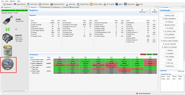
We have already started the learning cycle by enabling IT and discharging the battery. Currently, the pack is in the relaxation state. We have attached the BQStudio screenshot for reference.

  • Could you please confirm if we are proceeding correctly?

  • Are there any additional steps we need to take care of during this process?

    Fig (1) : Before starting the process, after IT Enable


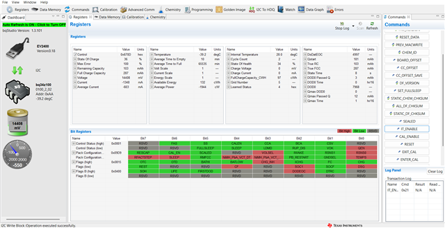
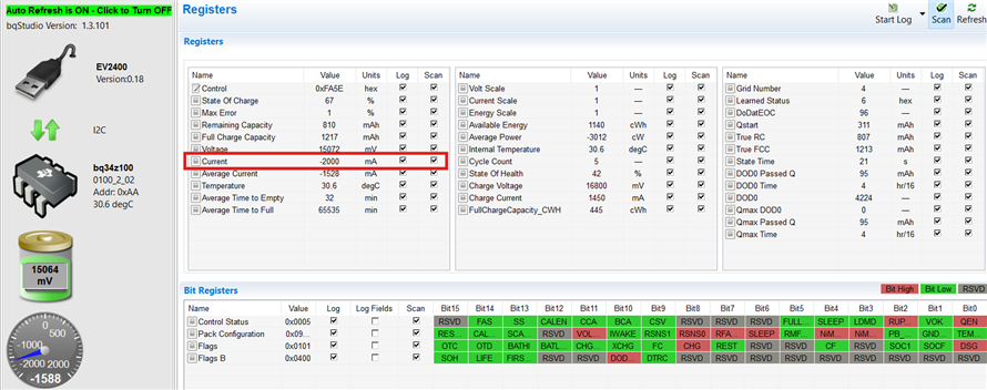
    Fig (2) : After started the initial discharge process.


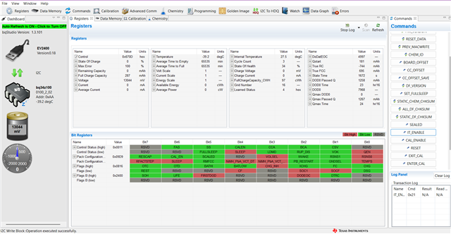
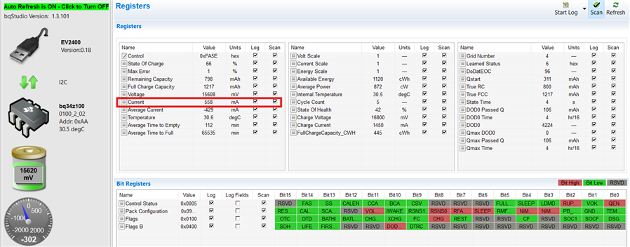
    Fig (3) : Now at the relax state for 5 hours 

We also observed that the registers are updating during discharge and relaxation, and the State Time is changing. We will share the register data for your reference as well.

Looking forward to your guidance.

Thanks & Regards,
Akin

  • Additional Observations / Doubts:

    1. Now the REST bit is high and the RUP_DIS bit is low, which we understand indicates the relaxation is completed. Is that correct?

    2. We have started the charging phase with 1A charging current, but the gauge is reporting only around 500 mA.

      • Please note: Voltage and current calibration was already done before starting this process.

      • Current was calibrated separately during a discharge process (not during the learning cycle).

      • What could be the reason for this mismatch in reported current?

    3. In the application report, it is mentioned as the [OCVTAKEN] flag, but in BQStudio we are seeing the REST flag. Are these equivalent?

    4. We have not calibrated the temperature yet, and we noticed that the Qmax is not updating.

      • Can we calibrate the temperature in between this process, or should it be done only before starting the learning cycle?

    Looking forward to your guidance and clarifications on the above points

    Fig(4) : Indicating the charging phase after relax but the charging current is 1A , showing only 500mA


    Thankyou,
    Akin

  • Hello,

    This question has been assigned and will be reviewed when possible, in the meantime please attach associated .gg/.log file.

    Thank you,
    Alan

  • Hi,

    However, while setting the Term Voltage, it is showing in red color and we are not able to write it.

    This is because the value you are trying to enter exceeds the max value for this parameter.

    You will need to use a voltage scaling factor, however, are you sure 12V is the cutoff voltage for a single cell in your battery pack, this seems high in my opinion.  

    The learning cycle will fail until this is fixed.

    What could be the reason for this mismatch in reported current?

    Please recalibrate the current so that it is accurate.

    Can we calibrate the temperature in between this process, or should it be done only before starting the learning cycle?

    please calibrate the temperature first.

    inaccurate current, voltage or temperature reading sill cause the learning cycle to fail.

    In the application report, it is mentioned as the [OCVTAKEN] flag, but in BQStudio we are seeing the REST flag. Are these equivalent?

    these are similar but not the same, the trm describes each bit.

    please log your next learning cycle attempt after making the above changes and share the results once available. 

    Regards,

    Diego

  • Hi Diego,

    As mentioned earlier, we are still not getting proper current readings after calibration.

    • We calibrated the current as per the Technical Reference document at –2000 mA. While discharging at 2A, the readings are correct (screenshot attached for reference). However, when charging with 1A, the current displayed is highly inaccurate, showing only about 500 mA (screenshot also attached).

                                   Fig(5): Discharging with 2A after calibrating the current to -2000mA


                                    Fig(6): Charging with 1A after calibrating the current to -2000mA

    • To verify, we then calibrated the gauge while charging at 1000 mA. In this case, the charging current was displayed correctly at 1A, but during discharging at 2000 mA, the measurement again became widely inaccurate.

    We have also calibrated the CC offset and board offset in no-load condition as mentioned in the Technical Reference document.

    Could you please advise on what might be causing this mismatch and how we can resolve it?

    Looking forward to your guidance at the earliest.

  • Hi,

    What are your CC gain and CC delta values?

    What size sense resistor are you using?

    Regards,

    Diego

  • Hi Diego,

    The current reading issue was identified as being caused by a parallel current path while connecting the charger. We typically use a Type-C cable for charging, and during connection, a parallel path was formed due to the shield ground and ESD ground being shorted. This resulted in variations in the current readings.

    Now, while performing the learning cycle (discharge → relax → charge → relax), we are facing another issue. As per the expected sequence, the Update Status should progress from 000405. However, in our case, after reaching 04, it directly transitions to 06 after the charging relax phase. From our understanding, 06 should only occur after the discharge and relax cycle following this charging step.

    Could you please clarify why the Update Status is changing in this manner?

    Regards
    Akin

  • Hi,

    However, in our case, after reaching 04, it directly transitions to 06 after the charging relax phase.

    This is ok, this means the gauge updated both the Qmax value and Resistance tables with the same ocv measurement. If you have reached update status 6 and your ra tables have updated, then your learning cycle is complete.

    Regards,

    Diego