UCC28070: UCC28070 Input current distortion

Part Number: UCC28070

Tool/software:

Hello,

I am working on 500W PFC design using the UCC28070EVM. I recalculated component values using the Set-up Tool SLUC114 Rev 2.0 and applied these changes to the EVM. The boost inductors are MnZn (example Wurth 74437429203151) as recommended by TI some years ago when I was working on a similar design.

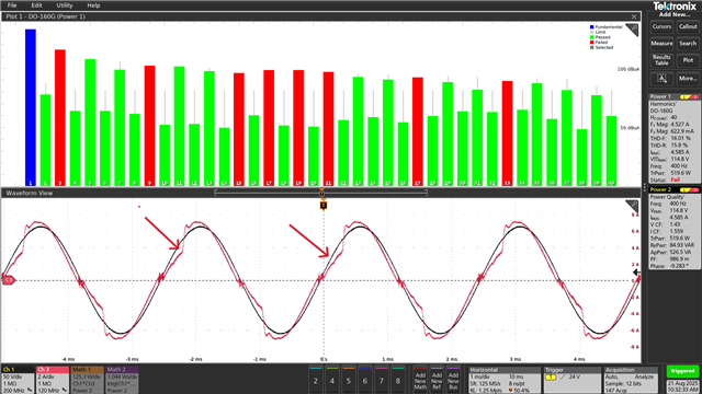
The results of the component changes to the EVM revealed input current distortion, as shown in the image below, that I was unable to overcome with adjustments to the component values. The current distortion causes non-compliance with the DO-160G Current Distortion requirement.

Is the cause of this current distortion a circuit set-up issue? 

It appears to be a specific condition that causes the distortion, since it occurs after the zero crossing.

The attached zip file contains the Ver 2.0 Set-up tool with my design inputs and with the component values used to set up the circuit that produced the waveform in the image below.

Please review and let me know if I can provide further information.

Thanks!

    UCC28070_Design_Tool_2.0_10Sep2025.xlsm.zip


  • Hello Gord, 

    There are a few different possibilities that I suggest to explore.

    1.  The Excel tool indicates Lb > 121uH should result in CCM current over the entire line cycle.  150uH inductors should meet this requirement, yet the waveform looks like it has elements of DCM along the rising edge of the voltage.  Please verify that your inductor currents are operating in CCM at the test conditions for THDi. 

    2. Check the response of the CAOA and CAOB outputs to see if their voltages are distorted in the region of the line distortion (arrows). Normally, the CAOx outputs should look like inverted rectified sines.  High Vcaox results in wide duty cycles, low Vcaox results in narrow duty cycles. Narrow duty at the zero crossings would result in too-low of input current. 
    Check to see if Vcaox is somehow kept lower than normal during the distortion time.     

    3.  Check the VINAC input waveform for distortion compared to the actual rectified line voltage.  The VINAC diodes D5 and D6 on the EVM may not be suitable for 400Hz input and may have reverse-recovery or other distortion effects on the VINAC signal.  Also, verify that VINAC and VSENSE both have the same resistor divider strings and that filter caps C2 and C6 (on controller board) have been reduced to ~680pF, per recommendation at cell D69 of the Excel tool.
    Ideally, VINAC should be a scaled replica of the rectified AC line voltage, without any distortions that are not present in the high-voltage waveform. 

    4.  Check that the IMO-pin voltage follows the VINAC waveshape without adding any additional distortion.  

    5.  Check that you are getting the ~96.5% max duty cycle near the zero crossings that is programmed at the DMAX pin (where Rdmx = 34.8kR per Excel tool). 

    Regards,
    Ulrich