


Other Parts Discussed in Thread: TPS65987D,
Tool/software:
Hi,
I am evaluating the TPS25751S for a printer application, and I have several questions regarding the specification descriptions and behavior of power/data roles.
Q1.About the specification on TI homepage
➤ TPS65987D
・Power role DRP, Sink, Source
→DRP. (Depending on negotiation, Sink or Source), Sink, Source
・Data role DFP, DRD, UFP
→DRD. DFP (Host), UFP (Device)
➤ TPS25751S
・Power role DRP, Sink
→DRP. (Depending on negotiation, Sink or Source), Sink (no Source)
・Data role DFP, DRD, DRP ← UFP?
→Is the red “DRP” actually a mistake for UFP? If it is a mistake, then it should be the same as TPS65987D.
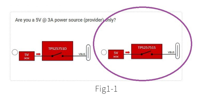
✓ In the USBPD Application Customization for TPS25751, it is possible to set Power Source only as shown in Fig.1-1.
But in the above specification of Power role, there is no description of “Source”.
Does this mean the operation has a different meaning?
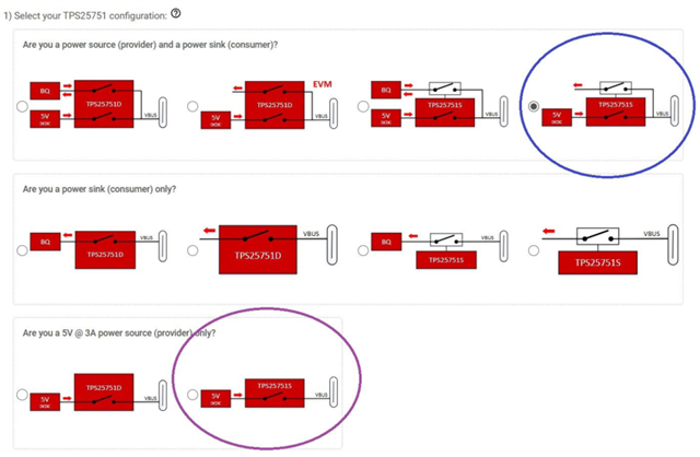
Q2. About candidate selection with ◎ mark in TPS25751S setting
・Our end device is a printer. The communication port is being replaced from USB Type-B to Type-C, and it is assumed to supply power to the upstream host.
However, if a notebook PC (that does not require power supply) is connected, the upstream side may supply 5 V / 500 mA to VBUS.
In such a configuration, should we select the blue circle or the purple circle?
・If selecting the blue circle, sink current is not particularly needed, so we do not attach an external FET.
In this case, must the circuit configuration be exactly like this?
・If selecting the purple circle, PDC will be Source only.
In that case, if the upstream device is also Source only, won’t the two Sources collide and cause a problem?
Q3. In Web settings the following order appears. Is it correct to understand that processing is executed in this order?
◯ Power role:
・Process Swap to Sink → Swap the process to Sink
・Initiate Swap to Sink → Start swap to Sink
・Process Swap to Source → Swap the process to Source
・Initiate Swap to Source → Start swap to Source
◯ Data role:
・Process Swap to UFP → Swap the process to UFP
・Initiate Swap to UFP → Start swap to UFP
・Process Swap to DFP → Swap the process to DFP
・Initiate Swap to DFP → Start swap to DFP
For example, sometimes “Process” is checked but “Initiate” is not checked.
What is the meaning of such setting?
Looking at the wording, it seems like:
-
“Process Swap to UFP” means to accept the request to swap to UFP from the upstream device,
-
while “Initiate Swap to UFP” means the PDC side itself initiates the swap to UFP to the upstream device.
Is this interpretation correct?
Thanks,
Conor
