


Tool/software:
We use four TPS62867RQYR on one of our boards to generate the following 4 voltages:
- 0.95V
- 1.2V
- 1.8V
- 3.3V
from the common 4.2V input voltage. All 4 instances show the correct 220nH inductor on the schematic: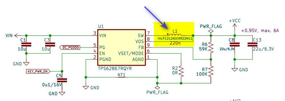
However, the BOM has by mistake listed a 2.2uH inductor, more specifically the DFE322520F-2R2M=P2 (3.3A, 0.04 Ohm). Do you see an issue with it in the situation where the consumption current does not exceed 2.5A?
From what we can see, the buck and board function properly, and we wonder whether it makes sense to go through the trouble of changing the inductor to the value specified in the datasheet, specifically to the 240nH DFE201612E-R24M=P2 (5A, 0.02 Ohm).
Could you please provide your expert advice on what may go wrong, if anything, as a consequence of this BOM mistake?

