


Tool/software:
Hello,
I am working on a 3S 18650 cell BMS design. I am confused on some of the reference schematics where for the LED pins a 1A BJT was used and there were no resistors to limit the current. In my design I put a MMBT3904 which is a 0.2A IC, 40V, NPN. If I am assuming correctly, CAP1 should be 3.3V from its internal LDO, C3 in my case is the top of my 3rd battery cell so 4.2*3=12.6V when fully charged. I am using ASMM-CF03-AP402 for my LEDs, they have a Vf of 1.7V to a maximum of 2.6V. Each pin for these LEDs can only sink 3mA right?
So for my current limiting resistors I did:
R = (V_pk - V_f(min)) / I_LED = (12.6 - 1.7) / 3m = 3.63k -> 3.9k
I = (V_pk - V_f(min)) / R = (12.6 - 1.7) / 3.9k = 2.79mA
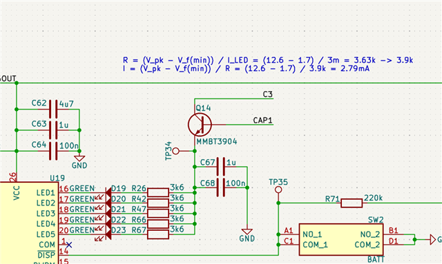
I put a resistor per LED. Will this work? Can I use these LEDs, this BJT, and did I setup the resistors correctly?
