This thread has been locked.

If you have a related question, please click the "Ask a related question" button in the top right corner. The newly created question will be automatically linked to this question.

BQ25630EVM: can't make the battery full of charging on the EVM

Part Number: BQ25630EVM
Other Parts Discussed in Thread: BQ25630, EV2400,

Tool/software:

Hi TI expert,

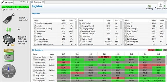
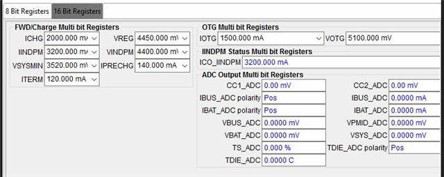
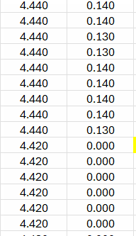
i have one problem that the battery can't be charged full (my battery CV is 4.45V) on the EVM of the BQ25630 when i set the below parameter (as below capture) and others kept as default setting, even if the charger IC entered the termination current and stopped to charge (as below charging flow data), but the battery fuel gauge info still shown the 97% voltage not 100% when i read it by EV2400(as below capture). i don't know where parameters need to be set and configured on the EVM, could you please give some suggestion on that for me? thank you very much!

Parameter setting.

Battery charging flow.

Battery fuel gauge info.

  • Hi Jimmy, 

    Thank you for sharing details on your device configuration in your testing. Please see my comments below. 

    How do you have the BQ25630EVM, fuel gauge, and battery connected in your test setup? If possible please help to share a picture for my reference. I ask about this because the BQ25630 determines end of charge voltage based on the voltage measured by 'BATP' (battery voltage sense) pin. On the EVM this pin is routed to the J4 Bat terminal block. Additional wiring from EVM to fuel gauge to real battery terminal may be the cause of minor voltage drop and battery only charging to 97% rather than 100% as a result. 

    In the final product recommended design would be to connect BATP voltage sense pin as close as possible to actual battery terminal for most accurate battery voltage sense, which will then allow proper charge to full charge voltage. 

    Best Regards,

    Garrett 

  • Hi Garrett,

    thank you for the quick response. the following picture is the setup of the battery charging, shared it with you for reference. hope to get your suggestion about the battery full of charging issue solving.

  • Hi Jimmy, 

    Thank you for your reply. 

    What voltage do you measure via a multimeter at TP35 (BATP) on the BQ25630EVM when battery charge current is <150mA? 

    I would also like to reiterate my key point that battery voltage sense function of BQ25630 will be optimized on a custom/end application PCB where BATP can connect to battery terminal rather than testing with the EVM board connected to gauge board and then battery. The test setup is the most likely cause of gauge device indicating 97% charger rather than 100%. 

    You can achieve a more full charge by increasing VREG setting a small amount, such as by 10-20mV, or reducing ITERM setting below 120mA, but these configuration changes may not be recommended for testing with your real battery. 

    Best Regards,

    Garrett

  • Hi Garrett,

    thank you for the explanation. Yes, i fully understood your meaning that the BATP pin may need to do the optimization on the end application PCB, and i tested the BATP voltage on the EVB, which shows the voltage looks like same as the Battery voltage, there is no gap of voltage. (as below capture). meanwhile, based on your comments, I've tried the ITERM setting to 100mA from original 120mA, after a moment, the battery can be entered the 100% energy display on the BQ studio tools. (as below capture). but i am not sure whether it is realistic root cause or not on this issue? because the voltage of the battery fuel gauge hasn't reached the target voltage (4.45V). any comments on that?

  • Hi Jimmy, 

    Thank you for checking BATP voltage verse BAT. Please see my comments below. 

    but i am not sure whether it is realistic root cause or not on this issue? because the voltage of the battery fuel gauge hasn't reached the target voltage (4.45V). any comments on that?

    The voltage you measure at BATP, 4.44V, just before termination is within the expected +/- 0.3% accuracy of VREG setting. There will always be some minor variation from the VREG set point. 

    Lowering the ITERM current setting is a valid way to ensure you are charging to a fuller battery capacity. Additionally, the topoff timer feature of the BQ25630 is another option which can be enabled to ensure battery is charged to 100% capacity. Topoff timer can be enabled in REG0x15[4:3]. 

    Best Regards,

    Garrett 

  • Hi Garret,

    thank you for the support and suggestion. based on your comments, I've tried the testing on the EVB with the Top-off timer setting, after completed a battery charging cycle, the battery can be charged to the full. but the charging duration time is longer (about 11mins) than before setting (ITERM:100mA), detail as below comparison capture. Do you know what reason it is?

    Here I have another question that the CE pin function of the charger IC, currently, our project has a MCU to connect it. but I am not sure whether this function should be controlled by the MCU or not, because the charger IC can be automatically stopped the charging progress when the battery triggered the termination current. if we used a GPIO of the MCU to control the CE pin of the charger IC, it looks like a redundancy design. what do you think on that?

  • Hi Jimmy, 

    Please see my comments below. 

    the battery can be charged to the full. but the charging duration time is longer (about 11mins) than before setting (ITERM:100mA), detail as below comparison capture. Do you know what reason it is?

    It is expected that overall charge time will be longer with top-off timer enabled. The feature continues charge for 15, 30, or 45 minutes after termination is reached depending on configuration. 

    It appears your testing has confirmed that charge time with ITERM = 120mA + 15 minute top-off charge is longer than charge time with ITERM = 100mA. This is a reasonable result. 

    if we used a GPIO of the MCU to control the CE pin of the charger IC, it looks like a redundancy design. what do you think on that?

    You are correct that charge will automatically stop when charge cycle terminates. There is no need to change CE pin status in this case. With that said there are other reasons some customers want to be able to enable/disable charge via MCU control. Charge can be disabled via CE pin or EN_CHG bit, so you can choose to control charge enable/disable via I2C instead of via CE pin if you wish to save the GPIO pin for a separate purpose. 

    Best Regards,

    Garrett 

  • Hi Garrett,

    thank you for the support and explanation, right now, i think my questions are fixed. thank you very much.