BQ24292I: Unexpected current consumption with disable connection to a fully charged battery?

Part Number: BQ24292I

Tool/software:

I have a setup with the following schematics:

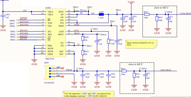
VIN is the Vbus of an USB-C Port to which the device is the peripheral/device, never the host.

Now what I am trying to do, is to disconnect the Battery (via I2C host) from the device for end of line measurements, where we want to see device consumption via Vbus (since the device is already assembled and the USB is the only connection to the outside). From my understanding, disabling charging via CE = high or CHG_CONFIG(REG01[4:5]) = 0 and disabling the BATFET via BATFET_Disable (REG07[5]) should do the trick (watchdog is also disabled). This seems to have the desired effect with a Battery that is not fully charged, but if I connect a battery with a voltage around VREG, I get additional consumption at Vbus of around 22mA and a load change on Vsys is no longer 1:1 reflected in that input current.
What could be happening there and how do I prevent it?

  • Hi,

    Could you please provide the following for the two cases you mentioned?

    1. The charger operating conditions such as VBUS (voltage at VBUS pin), IVBUS, VBAT (voltage at BAT pin), IBAT, VSYS, ISYS.
    1. All the charger register readings.

    Thanks,

    Ning.

  • 1. Vbus is USB, on my current setup I measure 4.7V . The issue occures at VBat >3.7V. Vsys is = Vbat before the Batfet switching and 4.19V if Batfet is disabled. IBat is 0mA. Ibus in that situation is 34mA instead of <8mA with no Battery or Battery below 3.7V (that's my issue). Unfortunately I can not currently measure ISys (I guess I should now work out how to measure this in our PCB).   ISys remains at ~6,3mA in either case.


    2. My registers are set up like this:

            {    .IINLIM = 0b010, //INPUT CURRENT LIMIT = 0.5A
                 .VINDPM = 0b0111,
                 .EN_HIZ = 0,
            },
            {
                 .Register_Reset = 0,
                 .I2C_WatchdogTimer_Reset = 0b1,
                 .CHG_CONFIG = 0b01,
                 .SYS_MIN = 0b111,
                 .BOOST_LIM = 0b0,
            },
            {
                 .ICHG = 0b000111,
                 .FORCE_20PCT = 0,
            },
            {
                 .IPRECHG = 0b0001,
                 .ITERM = 0b0001,
            },
            {
                 .VREG = 0b100110,
                 .BATLOWV = 0b1,
                 .VRECHG = 0b0,
            },
            {
                 .EN_TERM = 0b1,
                 .TERM_STAT = 0b0,
                 .WATCHDOG = 0b00,
                 .EN_TIMER = 0b1,
                 .CHG_TIMER = 0b01,
            },
            {
                 .BAT_COMP = 0b000,
                 .VCLAMP = 0b000,
                 .TREG = 0b00,
            },
            {
                 .DPDM_EN = 0b0,
                 .TMR2X_EN = 0b1,
                 .BATFET_Disable = 0b0,
                 .Reserved = 0b010,
                 .INT_MASK = 0b11,
            }

    Status read says PG_STAT = 1 and no faults

    Edit: measured ISys

  • Ok, so I gathered that the effect is related to SYS_MIN (REG01[1:3]), which I had set to 3.7V . If Vbat is above SYS_MIN (while charging is disabled and batfet is disabled!), I have the massive increase in consumption. What is happening at that point, and how do I prevent (or enforce) it to get stable behavior?
    My understanding from the datasheet is that exactly nothing should happen at that point since "battery charging is disabled or terminated".

  • Hi,

    It's still not very clear.

    1.IBAT=0mA, what are the following?

    1)The charger operating conditions such as VBUS (voltage at VBUS pin), IVBUS, VBAT (voltage at BAT pin), IBAT, VSYS, ISYS.

    2)All the charger register readings.

    2. When Ibus situation is 34mA, what are the following?

    1)The charger operating conditions such as VBUS (voltage at VBUS pin), IVBUS, VBAT (voltage at BAT pin), IBAT, VSYS, ISYS.

    2)All the charger register readings.

    Thanks,

    Ning.

  • Like I said the only difference in the environment is VBAT.

    1. Iloss = 1.4mA (Ibat is 0mA in both cases)
    1) VBUS = 4.7V IVBUS= 7,8mA, VBAT = 3.6V IBAT=0mA, VSYS= 4.19V, ISYS= 6,4mA
    2) Settings: 

    {    .IINLIM = 0b010,
     .VINDPM = 0b0111,
     .EN_HIZ = 0,
    },
    {
     .Register_Reset = 0,
     .I2C_WatchdogTimer_Reset = 0b1,
     .CHG_CONFIG = 0b00,
     .SYS_MIN = 0b111,
     .BOOST_LIM = 0b0,
    },
    {
     .ICHG = 0b000111,
     .FORCE_20PCT = 0,
    },
    {
     .IPRECHG = 0b0001,
     .ITERM = 0b0001,
    },
    {
     .VREG = 0b100110,
     .BATLOWV = 0b1,
     .VRECHG = 0b0,
    },
    {
     .EN_TERM = 0b1,
     .TERM_STAT = 0b0,
     .WATCHDOG = 0b00,
     .EN_TIMER = 0b1,
     .CHG_TIMER = 0b01,
    },
    {
     .BAT_COMP = 0b000,
     .VCLAMP = 0b000,
     .TREG = 0b00,
    },
    {
     .DPDM_EN = 0b0,
     .TMR2X_EN = 0b1,
     .BATFET_Disable = 0b1,
     .Reserved = 0b010,
     .INT_MASK = 0b11,
    }
    Status:

    2. Iloss = 23.4mA

    1) VBUS = 4.7V IVBUS= 31,2mA, VBAT = 3.8V IBAT=0mA, VSYS= 4.19V, ISYS= 6,4mA

    2)Settings:

    {    .IINLIM = 0b010,
     .VINDPM = 0b0111,
     .EN_HIZ = 0,
    },
    {
     .Register_Reset = 0,
     .I2C_WatchdogTimer_Reset = 0b1,
     .CHG_CONFIG = 0b00,
     .SYS_MIN = 0b111,
     .BOOST_LIM = 0b0,
    },
    {
     .ICHG = 0b000111,
     .FORCE_20PCT = 0,
    },
    {
     .IPRECHG = 0b0001,
     .ITERM = 0b0001,
    },
    {
     .VREG = 0b100110,
     .BATLOWV = 0b1,
     .VRECHG = 0b0,
    },
    {
     .EN_TERM = 0b1,
     .TERM_STAT = 0b0,
     .WATCHDOG = 0b00,
     .EN_TIMER = 0b1,
     .CHG_TIMER = 0b01,
    },
    {
     .BAT_COMP = 0b000,
     .VCLAMP = 0b000,
     .TREG = 0b00,
    },
    {
     .DPDM_EN = 0b0,
     .TMR2X_EN = 0b1,
     .BATFET_Disable = 0b1,
     .Reserved = 0b010,
     .INT_MASK = 0b11,
    }
    Status:

    So the effect seems to be down to VSYSY_STAT being in VSYSMIN regulation or not. But I don't understand how the regulation can be different depending von VBAT if BATFET is disabled (so "shipping mode").

  • Hi,

    You mentioned below. What is Iloss referring to?

    Iloss = 1.4mA (Ibat is 0mA in both cases)
    1) VBUS = 4.7V IVBUS= 7,8mA, VBAT = 3.6V IBAT=0mA, VSYS= 4.19V, ISYS= 6,4mA
    Iloss = 23.4mA
    1) VBUS = 4.7V IVBUS= 7,8mA, VBAT = 3.8V IBAT=0mA, VSYS= 4.19V, ISYS= 6,4mA

    Thanks,

    Ning.

  • Damn, Of course the loss is additional consumption on IVBUS, 

    so  1.1      VBUS = 4.7V IVBUS= 7,8mA, VBAT = 3.6V IBAT=0mA, VSYS= 4.19V, ISYS= 6,4mA
    and 2.1 VBUS = 4.7V IVBUS= 31,2mA, VBAT = 3.8V IBAT=0mA, VSYS= 4.19V, ISYS= 6,4mA

    (edited above as well)

  • Hi,

    Did you test on the EVM under the same conditions?

    Thanks,

    Ning.

  • I don't have an EVM.
    Do you have ANY pointers where I might look additionally on my hardware?
    Or in general what combination of settings do YOU propose for my use case of wanting to use the IC as a simple regulator for a certain time even though the battery is connected. Are my settings even correct?

  • Hi,

    Please visit https://e2e.ti.com/support/power-management-group/power-management/f/power-management-forum/877725/faq-bq24192-bq2419x-schematic-review-and-pcb-layout-design-tips for BQ2419X: Schematic Review and PCB Layout Design Tips.

    Did you test a single board or multiple boards?

    Thanks,

    Ning.

  • I tested multiple Boards and all behave identical. The schematics seem to fit the design tips as well.
    So to reiterate:
    Or in general what combination of settings do YOU propose for my use case of wanting to use the IC as a simple regulator for a certain time even though the battery is connected. Are my settings even correct?

  • Hi,

    When battery is connected, please refer to 8.3.2.1 Narrow VDC Architecture on the d/s for the charger operations. It's hard to have a fixed SYS output like a simple buck converter when the battery voltage rises above the minimum system voltage.

    Thanks,

    Ning. 

  • So BATFET_Disable does not actually disconnect the battery?

  • Hi,

    When charge is disabled, the current can not flow from SYS to BAT, but the current may still flow from BAT to SYS.

    To block current from both directions, please disable the BATFET by REG07[5]=1). Please refer to 8.3.1.2.1 BATFET Turn Off on the d/s.

    Thanks,

    Ning.

  • This is what I did! As you can already read in my first post. Changing the bit REG07[5], called BATFET_disabled, to 1.
    But I get different behavior of the BQ24292I depending on VBat anyways. This is why this Thread exists!

  • Hi,

    When disable the BATFET, there's no charge/discharge current IBAT as you observed IBAT=0mA, but this does not impact on VBUS current IVBUS and the device may still switches to support SYS.

    In order to minimize the IVBUS, please enable HIZ via REG00[7] bit.

    Thanks,

    Ning.

  • And it should switch, because it is the only power source. But I want it to switch in a reproducible manner, Independent of VBat, and that does not seem to happen even with BATFET_disabled set.

  • Hi Oliver,

    It looks like Battery voltage is having an impact on input current, regardless of the BATFET being disabled. Can you try a couple of items to better understand the behavior:

    - It appears VBAT has a direct connection to the MCU through a pair of resistors. Can you depopulate R612 and rerun the test? Sometimes unexpected power-paths through the MCU or SYS signals can have an unexpected impact on device behavior.

    - Can you try this test with your load disconnected? This is to try to isolate behavior to the BQ Charger to ensure there isn't another factor that might be impacting current consumption.

    - Can you provide any waveforms of VIN, VSYS, VSW, and VBAT under the two different conditions to contrast the device behavior?

    Best Regards,

    Juan Ospina

  • Unfortunately I am currently not in the office (due to illness -.-), so I have to do those specific measurements later.
    The "unexpected power path" is through 300kOhm to a pin set to analogue, which should be in the MOhm range, so I highly doubt that multiple mA consumption an be influences by that.
    Still for me the question remains whether YOU think the described behavior of Vbat influencing the regulator with BATFET disable is even possible considering the design of the chip. All measurement until now propose exactly that explanation.

  • Hi,

    The IVBUS referred to is not a d/s spec. There's no much to do with it.

    Thanks,

    Ning.