LM51772: SCHEMATIC REVIEW / DEVICE DOESNT PROVIDE POWER

Part Number: LM51772
Other Parts Discussed in Thread: LM51770

Tool/software:

Dear TI team,

We have been experiencing the lm51772 through the evaluation module succesfully even if the evaluation board would only accept 48V output capabilities whereas we are aiming for a 55V output

We have been going to design and are facing trouble:

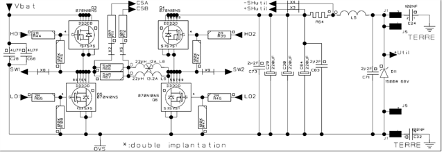
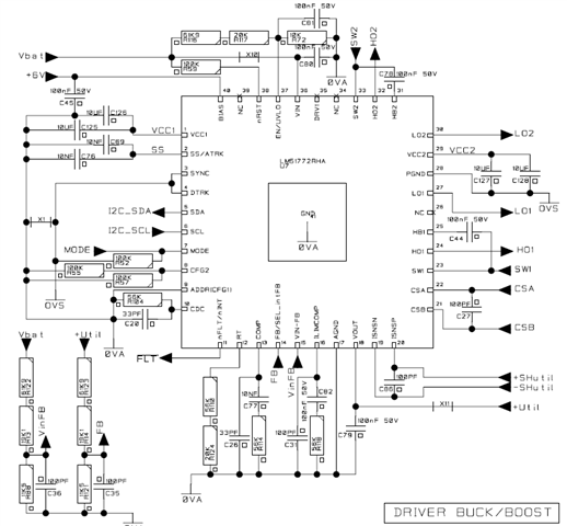
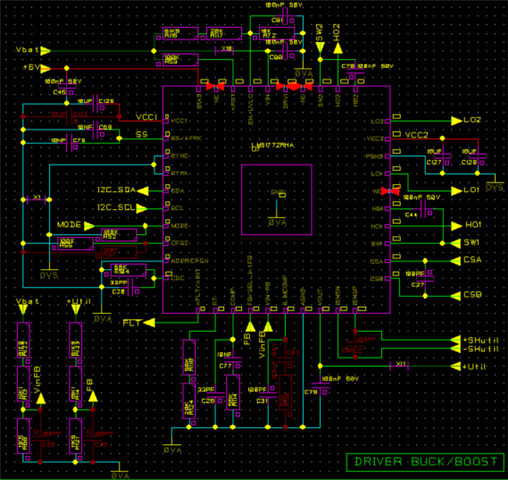
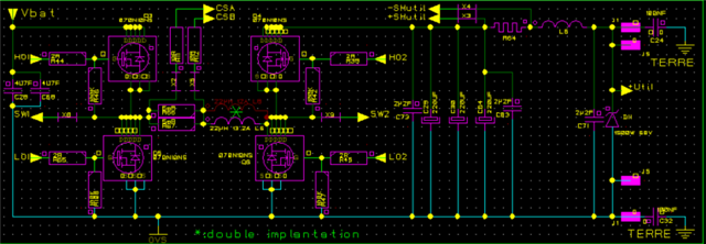
We are supposed to control the device over I2C. the input is a 17V battery (please see design file attached) 

With the attached schematics: 


- The I2C works (communicate)

- the configuration is coupy paste from the evaluation board

- the output voltage seems to be following the command, however, over 30V of command the output voltage doesn't follow the command and the maximum reachable voltage is 33V
The power we may draw is limited to a few mA (50mA maximum)


Do you see any issues with the schematic (we have been modifying FBout which is now tied to VCC2 for I2C communication, the vbias voltage has also been modified to be set on 10V )

Thanks,

Edgar

  LM51772_Buck-Boost_Quickstart_Tool_V1_2_0.zipregs_Module_Eval_15V_Sortie24.zip

  • Hello Edgar,

    The maximum voltage you can get with the I2C programming is 48V. If you want to get to a higher output voltage, I think the LM51770 would be the right device for you.

    BTW, could you please share the schematic somehow in a different way? It is not very clear, so I can hardly read it.

    Best regards,
    Brigitte

  • In this schematics, L8, C125,C86,C82,R118,C36,C35,R57 are not populated ..

    Regarding the 55V Volt ouptut, we did ask on this forum before goiing into design and stefan did answer this shall be feasible  

    Hi Edgar,

    this caps are rated for 50V only - so after replacing them with 100V types e.g. (GCJ188R72A104KA01D) you should be OK for output voltage up to 55V."

    thanks for help

  • Hello edgar,

    Please let me clarify about the output voltage:

    - I2C programmable output voltages are up to 48V on the LM51772, see datasheet https://www.ti.com/document-viewer/LM51772/datasheet#GUID-ABE962C5-68FD-43F8-8D41-23762A2D01FB/GUID-FF1276AD-B2D0-49CC-A426-77CCBA6ECAC9

    - With the feedback divider, you can set the output voltage higher.

    - The OVP2 worst case minimum threshold is at 53.5V, so I recommend not going above this voltage for the output voltage setting. (If you are going higher, some devices might trigger OVP2.)

    Is it possible for you to set the output voltage with the external feedback divider and is it ok for you to set the output voltage to a maximum of 53.5V?

    Best regards,
    Brigitte

  • Dear Brigitte, 

    We gonna try in the next days. However, we would need to use I2C with the device anyway and this doesn't seems to be working ? Did you had time to review the schematics and see if something seems to be abnormal ? 

    Thanks,

    Edgar

  • Hello Edgar,

    Do you have pull-up resistors on the I2C pins? Can you check if the device reacts on the I2C when you put it in standby with EN around 1V?

    Here the comments to the schematic:
    - Exchange L5 with a 0ohm resistor to check if this filter causes an issue.
    - Can you please check if the problem is gone when you increase the capacitance on the SS pin? I wonder if you are rinning directly into the SCP with just 20nF on the SS pin.
    - The sense resistor is very small for your requirements. Be aware that the current sense signal is a sensitive signal, so a bigger resistor here might help.
    - The average current sense signal needs as well a filter (2 Rs, 1C). In addition the resistor should be placed in the middle of the output capacitors. Possibly disabling this function for the moment might help to bring the device up.
    - The compensation of the average current limit might be a problem as well.

    Best regards,
    Brigitte