Tool/software:
Problem
I'm seeing unexpected voltage output and fluctuating current input on the TPS61220 that I've soldered on my custom PCB (details can be found below). I would kindly request help to debug what might be going wrong in my setup.
Context
I'm planning to incorporate a TPS61220 voltage boost converter in my project. To learn how to design the final PCB, I've designed a small PCB to test out just the boost converter. I've modeled the design to the TPS61220EVM-319 evaluation model.
Notes
- I'm a hobbyist/enthusiast without any electrical engineering background, so could well be that I made some silly mistake, any help is appreciated
 .
. - I don't have access to an Oscilloscope, but if there is something <$100 that would help with debugging, I'm okay with buying additional tooling.
Notes on the data below
- R1 and R2 are swapped around compared to the TPS61220 datasheet.
- I've used 180k instead of 178k resistor for R1 (in my datasheet)
- Therefore, I expect: VOUT = VFB × (R2 + R1)/R1 = 0.5 x (1000+180)/180 ~ 3.28V
Schematic and PCB
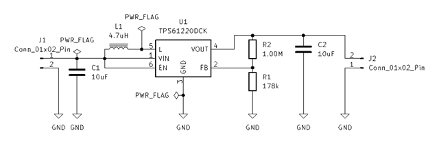
Figure 1: Schematic
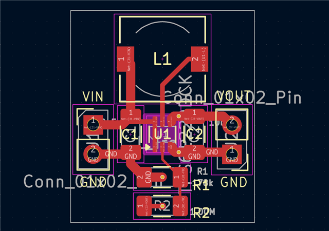
Figure 2: Front Layers PCB

Figure 3: Back Layers PCB
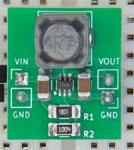
Figure 4: Photo of assembled PCB
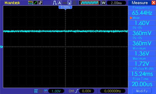
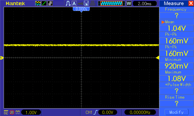
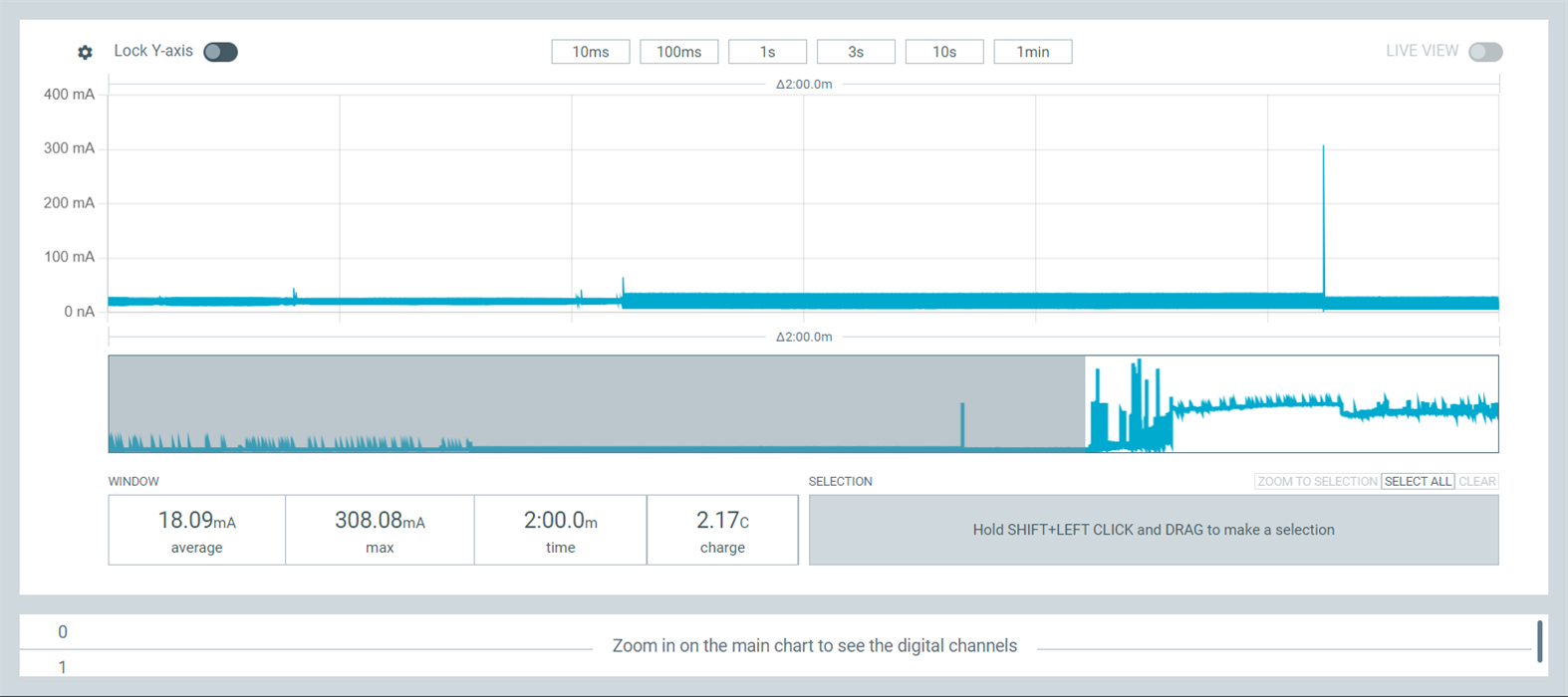
Measurements
Note: I don't have an Oscilloscope so the data collected below is from my Power Profile Kit II providing input voltage and current and a Multimeter measuring the output voltage.
| Input voltage | Output voltage | Stable | Power Consumption Screenshot |
| 1.00v | 1.56v | Yes | 1v.png |
| 1.50v | 1.57v | Yes | 1.5v.png |
| 2.00v | 1.57v - 1.59v | No | 2v - with load.png | 2v - without load.png |
| 2.50v | 1.92v | Yes | 2.5v.png |
| 3.00v | 2.30 - 3.00v | No | 3v.png |
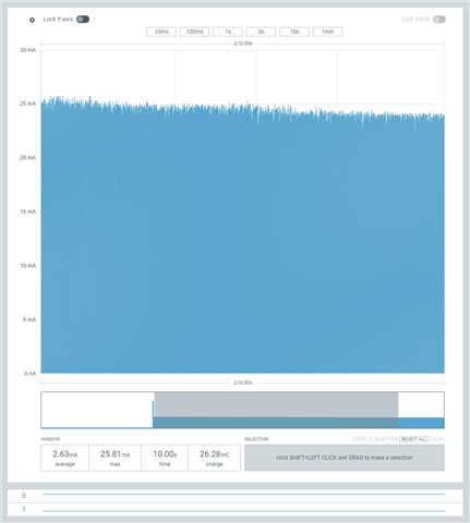
Figure 5: 1v.png
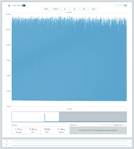
Figure 6: 1.5v.png
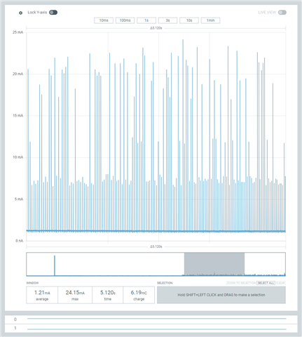
Figure 7: 2v - with load.png
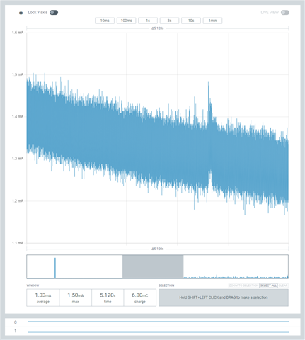
Figure 8: 2v - without load.png
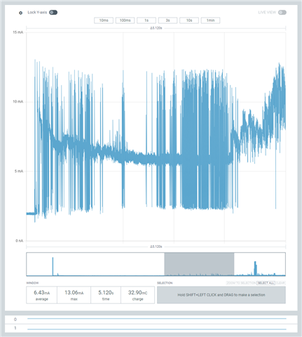
Figure 9: 3v.png