Tool/software:
Hello everyone,
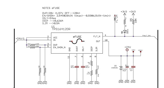
I am designing a power supply and I would like to use an eFuse to protect it, so I don’t need to replace a traditional fuse. I selected the TPS16412DRCR for this purpose.
Under normal operation the device works as expected. My input source is an AC/DC power supply rated at 24 V / 0.65 A.
-
When powered on, I can measure the 24 V at the output of the eFuse.
-
When I connect an electronic load at the output, the device behaves correctly: if I exceed the current limit threshold, the eFuse turns off the output, and once I reduce the load, the output voltage recovers as expected.
The problem occurs when I simulate a direct short circuit at the output. In this case:
-
The device is permanently damaged and ends up shorted between input, output, and GND.
-
Once this happens, the IC no longer operates.
-
I have desoldered and inspected the device and confirmed that it is physically burned.
-
If I replace the IC, the circuit works again, but the same failure happens when repeating the short-circuit test.
I have tried a few changes to improve the behavior:
-
Lowering the Rlim value to set a lower current limit.
-
Reducing the IDLY capacitor value.
Unfortunately, the result is always the same: the chip gets damaged during a short-circuit event.
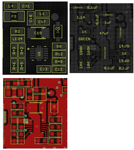
It is important to mention that I have already used this same eFuse reference in a previous design, and it worked fine in that case. For this reason, I am not sure if the current issue could be related to the layout. The only significant difference compared to the previous design, besides the Rlimit value (since I set a different current threshold), is that in this new PCB I added multiple thermal vias to GND under the thermal pad.
Could someone please provide guidance on what might be wrong with my configuration or PCB implementation?
Any help would be greatly appreciated.
Thanks in advance.