This thread has been locked.

If you have a related question, please click the "Ask a related question" button in the top right corner. The newly created question will be automatically linked to this question.

BQ25756: problem stability current charge

Part Number: BQ25756
Other Parts Discussed in Thread: BQ25858-Q1, , BQ25758

Tool/software:

Hello,

I use 2 BQ25756 chargers in parallel. From time to time, I experience losses of energy and sometimes power peaks that are generated on the output.

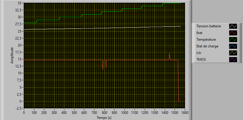
the measurements are made by a current sensor for the load current. it globalises the 2 chargers. the capture is sampled every 5s

I have 2 times in this capture where the current of charge are low and I have a current peak. 

the mos that separates the battery chargers is open and a 30V protection triggers from time to time. it indicates that at no load, the chargers generate a voltage peak exceeding 30V.

The schematic of the charger is  : chargeur.pdf. I have 2 times this schematic

After the charger, I have a mos in serie with a battery.

the CTN are placed close to the mos and the BQ25756.

I want to Have 15A of charge.

I periodically send data to the 2 chargers every 1s.

The code gererate every 1s is

/* desactive la charge */
    u8_Data[0] = 0x00u;
    e_I2CStatus = e_drv_bq25756_WrData(U8_REG_MPPT_CONTROL,&u8_Data[0],1u);
    if(e_I2CStatus != HAL_OK)
    {
        vd_drv_bq25756_ErrorHandler();
    }
    HAL_Delay(2ul);
    /* configure le control de temps */
       /*  configure le nombre de cellule en serie (bit 6-7) 0 = 1s .. 3 = 4s */
       /* bit 4-5 à 2 pour deglitch à 1024ms*/
       /* bit0 à 3 threslhold pour reactivation charge 50mV- 800mV offset 50mV step 50mV*/
       /* confiugration pour 2S 200mV de threshold */
       u8_Data[0] = 0x004u;
       e_I2CStatus = e_drv_bq25756_WrData(U8_REG_TIMER_CONTROL,&u8_Data[0],1u);
       if(e_I2CStatus != HAL_OK)
       {
           vd_drv_bq25756_ErrorHandler();
       }
       HAL_Delay(2ul);
       /* configure la detection de fin de charge : pas de détection fin  de charge et précharge desactivé */
       u8_Data[0] = 0x00u;
       e_I2CStatus = e_drv_bq25756_WrData(U8_REG_TERMINATION_CONTROL,&u8_Data[0],1u);
       if(e_I2CStatus != HAL_OK)
       {
           vd_drv_bq25756_ErrorHandler();
       }
       HAL_Delay(2ul);

       u8_Data[0] = 0x80u;
      e_I2CStatus = e_drv_bq25756_WrData(U8_REG_PIN_CONTROL,&u8_Data[0],1u);
      if(e_I2CStatus != HAL_OK)
      {
          vd_drv_bq25756_ErrorHandler();
      }
      HAL_Delay(2ul);

      u8_Data[0] = 0x00u;
       e_I2CStatus = e_drv_bq25756_WrData(U8_REG_POWER_PATH_REVERSE_CONTROL,&u8_Data[0],1u);
       if(e_I2CStatus != HAL_OK)
       {
           vd_drv_bq25756_ErrorHandler();
       }
       HAL_Delay(2ul);
       u8_Data[0] = 0xC0u;
       e_I2CStatus = e_drv_bq25756_WrData(U8_REG_REVERSE_MODE_BATTERIE_DISCHARGE_CURRENT,&u8_Data[0],1u);
       if(e_I2CStatus != HAL_OK)
       {
           vd_drv_bq25756_ErrorHandler();
       }
       desactive la charge */
           u8_Data[0] = 0x21u;
           e_I2CStatus = e_drv_bq25756_WrData(U8_REG_CHARGER_CONTROL,&u8_Data[0],1u);
           if(e_I2CStatus != HAL_OK)
           {
               vd_drv_bq25756_ErrorHandler();
           }
           HAL_Delay(2ul);

Best Regards,

Ludovic Micou

  • Hi Ludovic,

    These waveforms almost look like outliers to me. Can you verify that these currents are actually changing rather than an occasional inaccurate reading? This could maybe be from a shorter time scale on the oscilloscope triggering off of a lower current value.

    It would be helpful to also have a status and flag register reading in the code that occurs every 1s to see if the device reports any changes to operation.

    the mos that separates the battery chargers is open and a 30V protection triggers from time to time. it indicates that at no load, the chargers generate a voltage peak exceeding 30V.

    This would be the expected behavior at no load condition I think. What is the charge voltage of this application? From our FAQ Page:

    • Why are the D4 and D5 blinking alternatively when there is no battery connected?
      Most likely, the charger is going into charge-recharge oscillation. The charger will charge the output capacitors, reach the charge voltage and then terminate. The capacitor voltage will then fall and reach the recharge threshold of the charger. At recharge, the charger will start the process over again.

    Best regards,
    Michael Bradbourne

  • Hi mickael,

    I will create a programm next week for read the status for the 2 bq25756. and to measurment the current and voltage with a oscilloscope. 

    The voltage of charge are 29.4V. 

    Best Regards,

    Ludovic Mciou

  • Hi Ludovic,

    Sounds good. Thank you for this. On the oscilloscope, can you please also look at the SW1 and SW2 waveforms.

    Best regards,
    Michael

  • Hi Michael,

    I have a SW1 and SW2 waveform with the current charge and the voltage. I can’t catch the moment when the problem happens because I have too much noise measured on the oscilloscope.scope_1.xlsx

    I mesaure with a datalogger the current and the voltage and with a beagle the I2C datas. when I have the data the the problem, I will transmit it.

    Best regards,

    Ludovic Micou

  • Hi, 

    This the data of the I2C

    Chargeur.csv

    And the data of voltage battery and current input and charge. 

    UIChargeur.xlsx

    I will measure the control voltage of the mos on the oscilloscope.

    Best Regards

    Ludovic Micou

  • Hello, 

    the signal of sw1 is distorted due to an offset. here is a gate control curve Q8 and SW1.

    Q8-SW1.xlsx

    Best Regards,

    Ludovic Micou

  • Hi Ludovic,

    I don't see anything unusual reported in the status or fault registers. If the switching noise on the current measurement could be removed, that would be more helpful. I do have another suggestion.

    Can I confirm the inductor on the board? There is 2 on the schematic. Are they both populated on the board? If so, are they the same inductor?

    This image is from the BQ25858-Q1 datasheet, but the L/DCR requirement applies. I took a look at the inductor selection on the board (PA4349.103ANLT), and it looks like it violates the L/DCR. This has been known to cause a little instability. Does moving to a higher DCR inductor help the measurements you are seeing?

    Best regards,
    Michael Bradbourne

  • Hello, to help solve the problem, I want to look at the differencies in the documentations : 

    Concerning the pin 17 on BQ25756 :

    • the datasheet indicates a PGND signal, to be grounded
    • the User manual : BQ25756EVM Schematic, show a resistance R32 on this pin. Later in this same document (SLUUCT7D), the BOM gives a value of 3k ohm for R32
    • the design calc sheet mentions a Rmode with a fix value of 0 kohm

    Could you please clarify whether there is any specific information we should be focusing on with regard to pin 17 ?
    Thank you,
    Regards

  • Hi,

    The pin 17 is PGND for BQ25756. For BQ25758, the pin 17 selects buck-only. The pin functionality is different between the devices, but the converter architecture of the two devices is very similar as they are from the same product family.

    In either case, the converter architecture limits the L/DCR to 1.260ms. It is not well documented in the BQ25756 datasheet, so I pulled the table from another device in the BQ2575X family.

    Best regards,
    Michael

  • Hi,

    I tested with only one bq25756 active under 10A of load current. The inductance is replaced by a PA2247.103NLT. I always have the same problems but more frequent. The PA2267.103NLT have a Rdcr of 8.6mohm.
    I redid the measurements of SW1 and SW2 with probes to have less noise captured.

    SW1 and SW2 PA2247.csv

    Best Regards,

    Ludovic

  • Hi Ludovic,

    I am having difficulty plotting the data into a waveform. Are there any flags being set in the flag registers?

  • Hi,

    I don’t have a detected fault on fault_status, but only the status 1 which changes from 0x80 to 0x00 when it happens.

    this the log that I just generated with the problem.

    defaut self.csv

    Best Regards,

    Ludovic

  • Hello Ludovic,

    Thanks for being patient with me jumping into the thread. I have a few questions to help debug this.

    • Just to make sure, is the data logger fast enough to capture the switching waveforms? Do you see the same behavior with an oscilloscope?

    • Do the chargers have different termination current settings or do the chargers have the same termination current setting?

    • Does the battery have a battery monitor or a battery gauge? Is the battery monitor/gauge turning-off the protection FETs? Is the battery monitor/gauge throwing any flags?

    Best Regards,
    Ethan Galloway

  • Hello Ethan,

    The data logger can only have a step time of 10ms. I can't log the SW1 and SW2 with the data logger. With the oscilloscope, 

    The chargers are the same terminated charge. for now, I only use one charging path to solve the problem

    The battery have a monitor / gauge. the protection isn't activate. I don't  have a flag in the gauge. 

    Best Regards,

    Ludovic Micou

  • Hi Ludovic,

    The switching waveform during the low current event would be helpful to look at. The time scale of 10 ms is not enough to determine what the charger is doing to cause the current abnormalities. I do find it strange that not a single flag from the BQ25756 registers 0x25 to 0x27 though. I assume that the STAT1 and STAT2 pins do not change their state either?

    We recommend that the chargers have different charge termination levels. If the charge termination is set lower on one device, this will prevent both devices from trying to be voltage sources at the same time.

    Noted about the monitor/gauge.

    Best regards,
    Michael Bradbourne