This thread has been locked.

If you have a related question, please click the "Ask a related question" button in the top right corner. The newly created question will be automatically linked to this question.

TPSI2140-Q1: TPSI2140-Q1

Part Number: TPSI2140-Q1
Other Parts Discussed in Thread: TPS4141-Q1

Tool/software:

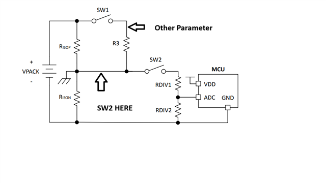
I am planning to use the TPSI2140-Q1 IC in my new design. My ADC shares the same reference as the battery negative. I referred to the Battery V– Reference Architecture shown in the TPSI2140-Q1 datasheet, and I would like to use a similar approach for battery voltage measurement in my system.

However, the issue is that if the isolation resistance fails, the measured battery voltage becomes incorrect, which is not acceptable. To address this, I am considering moving SW2 behind R3 so that even if the isolation resistance fails, the battery voltage measurement remains accurate.

Additionally, I plan to measure other battery parameters after SW1. Would this approach be acceptable, or do you recommend an alternative solution?

  • Hello Krushang Vakil,

    Thank you for reaching out to our team's E2E and with this Insulation Monitoring Architecture question using TPSI2140-Q1. 

    Our team is reviewing your request and will be in touch early next week

    Thank you for your patience. 

    Best regards,

    Hussain

  • Hello Krushang Vakil,

    Thank you for your patience as the team investigated your request. It is possible to move SW2 behind R3 in order to have an isolation resistance fail not impact a HV measurement taken with SW1 closed and SW2 open. While this makeshift approach would work, it would not be an optimized solution for HV battery measurement from a power consumption perspective, there is also an increased risk in exceeding the Avalanche current rating of SW2 if a High Potential test is conducted by applying High voltage from Vpack+ and Vpack- (tied together) to chassis GND.

    Relating to the first point on power consumption, High Voltage Measurement resistors are usually selected to be large in the double digit MOhm range to minimize power dissipation during measurement. For Insulation Monitoring, R3/RDIV1/RDIV2 resistors could be in the single digit Mohm range or even Kohm range in some cases to improve insulation measurement accuracy, therefore if these resistors are repurposed to also conduct High Voltage battery measurements, increased power dissipation is expected.

    Relating to the second point on Avalanche current rating of SW2, TPSI2140-Q1 is rated for 1mA of avalanche current, placing SW2 behind R3 as you suggested may be problematic in the case of the High potential test described above since the avalanche current through SW2 will be the sum of the currents through the R3 branch and RDIV1/RDIV2 branch of the circuit in the new configuration. The old configuration (SW2 in front of R3) limits the avalanche current to only the current through RDIV1/RDIV2.


    Alternative High Voltage Monitoring Solutions: 

    We commonly see High Voltage Monitoring implemented as a separate circuit utilizing a switch (TPSI2140-Q1 or discrete) and a resistor divider similar to the following: 

    If you would like to move to a small integrated solution for High Voltage monitoring with low power consumption and flexibility in High voltage divider ratios (programmable), we recommend our highly integrated HV monitoring solution TPS4141-Q1 which consolidates a switch and the HV resistive divider (shown above) in a single package.

    Thank you and we look forward to assisting in your design with TPSI2140-Q1/TPS4141-Q1.

    Best,

    Hussain