TPS25751: MCU does not see VBUS when VIN_3V3 supplies power to an uninitialized TPS25751 before USB cable from PC is connected

Part Number: TPS25751
Other Parts Discussed in Thread: CSD87501L

Tool/software:

I have observed a behavior that I cannot explain yet, and would like someone to point me to the documentation that could explain the behavior. Here is the scenario:

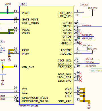
  • The TPS25751 chip is not initialized, not connected to EEPROM and not receiving I2C messages from the MCU.
  • A battery is connected to the board, supplying 3V3 to VIN_3V3 pin 32.
  • Then USB cable is connected to the board, supplying VBUS to pins 26 and 27.
  • GATE_VBUS and/or GATE_VSYS (pins 21 and 20) control CSD87501L which connects VBUS from the USB source to VBUS on the MCU. The VBUS connection to MCU measures 0V with this scenario.

The observation is MCU does not see VBUS.

However, if the USB cable is connected first (VBUS on pins 26 and 27), followed by the battery (3V3 on pin 32 VIN_3V3), the MCU continues to see VBUS (VBUS connection to MCU measures 5V). I have not found the reason for this behavior yet. Could you point me to the documentation that explains this behavior please?

Rex

  • Hi Rex, 

    Couple follow-up questions to help clarify the system: 

    1. What is the dead battery configuration (ADCIN1 and ADCIN2 pinstrapping) set for? Is it set for SafeMode or AlwaysEnableSink? 

    2. How is the PD config loaded? You mentioned EEPORM is not connected so I assume the MCU is pushing the PD config via i2C (Patch Burst Mode)? 

    3. When 3.3V is supplied to VIN_3V3 (battery connected) before the USB is plugged in, is the PD controller in APP mode (config loaded) or is it still in patch (PTCH) mode? 

    Thanks and Regards,

    Raymond Lin

  • Raymond,

    In this scenario, the PD config is not loaded. There is no communication between the MCU and the PD controller and there is no EEPROM. In our normal use case, PD config is loaded via I2C, but this scenario is another use case. ADCIN1 is connected to LDO_3V3 (config 7) and ADCIN2 is connected to LDO_1V5 (config 5) so it is set for AlwaysEnableSink.

    When 3.3V is supplied to VIN_3V3, the PD controller is in PTCH mode.

    Rex

  • Hi Rex, 

    This is expected behavior since TPS25751 is not in dead battery mode (powered from VIN_3V3 instead of VBUS). AlwaysEnableSink only applies when TPS25751 is first powered from VBUS. 

    Can you elaborate in this scenario where a battery is put into the system (TPS25751 powers on from VIN_3V3) why the MCU may not be loading the PD config? 

    Thanks and Regards,

    Raymond Lin

  • Raymond,

    Can you provide more details please? I do not follow what you mean by expected behavior. Is it documented in the manual? What does "not in dead battery mode" have to do with not allowing VBUS?

    The board may not always be in a product state, e.g. during provisioning, software may not have been loaded yet, or other software that does not initialize the PD controller is loaded.

    Rex