Other Parts Discussed in Thread: BQ25756, BQ34Z100
Tool/software:
Hi
I'm using 5S2P dump pack and standalone charger IC BQ25756 with BQ34Z100PWR-R2.
I have checked the datasheet, EVM schematics for reference. Still i have few doubts mentioned as below:
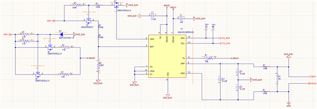
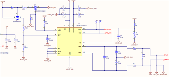
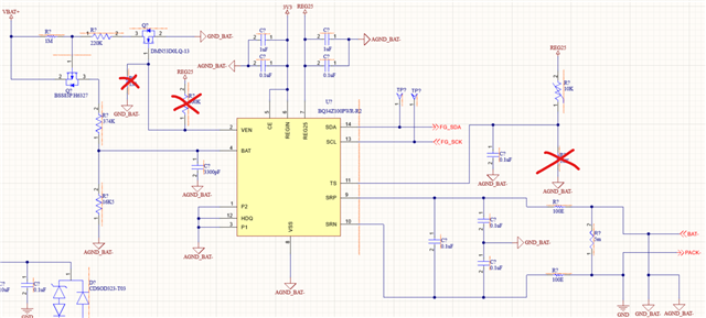
- Based on EVM BQ34Z100, do I need to provide the alert configuration? or can it be left unconnected? if it is not given, TS pin simply can be connected as with NTC 10K and powered with REG25.
- How to connect the BAT pin, since my battery is 5S2P? I don't want LED display. just need this fuel gauge for battery SOC monitoring.
- Since i don't use SW1, VEN cannot give input to Q4 fet, so Q5 won't turn on whole translated network won't happen right? So can i keep BAT pin with 16.5K pulled with GND and 3300pF tied to GND. no other mosfet required right? or explain me how it will work?
- REGIN pin input schematics ?