LM51772: Webench Design for a 5V DC does not work

Part Number: LM51772
Other Parts Discussed in Thread: LM51770, , CSD18540Q5B, CSD18512Q5B, CSD13202Q2, CSD17573Q5B

Tool/software:

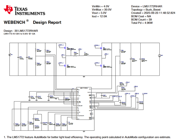
We need to design a power supply for 5V. Our Vin is 4-30V. Output is 5V up to 12A. We selected the LM51772RHAR based on Webench DC/DC design tool.

We do NOT have I2C implemented.

The folllowing is taken from the Webench Design Report

The following is the the schematic that we manufactured. 

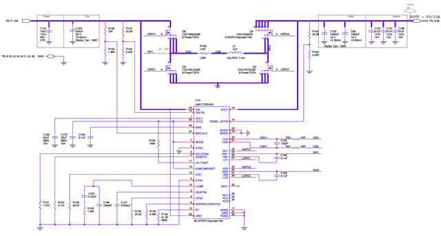
The 5V output drives a secondary 0.95V power supply using the TI TPSM82816SIER, plus a few peripherals etc. Very small load.

We are using a 12V/7A DC supply to power up the board. However the 5V is not working.

The first issue we noticed was that the Webench Rfbb1 supplied value (1.96K) is too low too enable this device. The manually calculated value show that it should be around 38K. We removed the Rfbb1 (0402) to allow EN_UVLO pin (now 12V) to enable this device. Now the 5V supply does switch on but the output looks like this.

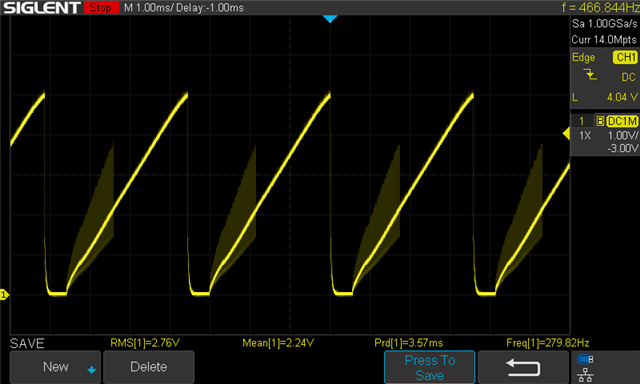
And the input and output caps are overheating. We think the LM51772RHAR maybe current limiting but we can't verify what the current limit should be given the none I2C adaption. From the schematic(s), you will notice that we are only implementing Rsns for sensing. I.e. no Risns.

Rsns = 1mR

Rdiff(s) = 10R, Cdiff = 120pF. From this we can calculate the ton,min = 150ns (Ref. section 7.3.10 Peak Current Sensor in the LM517772 datasheet)

We find that section 7.3.12 Current Monitor/Limiter is unclear given our system design (none I2C).

How can we verify if this supply is current limiting?

What else maybe causing this?

  • Hi Mark,

    If I2C is not needed, you could use LM51770, it should be easier to understand. And you could find very clear explanation on current limit in this apps note. Thank you.  Precise Current Limiter Over Wide Operation Voltages in Buck-Boost Converters

  • Hello Alicia,

    First of all thanks a bunch for quick response! It's Alex here, and I am working with Mark in the same team (device architecture). Here is a complete story a way I see it:


    1) LM51772 choice vs LM51770 was due to very strict PCB real estate limitations.
    2) Schematic capture was completely copied from your Webench tool on June 23, 2025 (and yes, we did compare Webench schematic produced from Webench link on product page, and separately from Webench tool itself by specifying part and parameters).
    3) We ordered x5 boards to prepare for client demo in October and since the rest of design is already verified from previous designs, 5V circuitry is the only "new" part.
    4) We received our boards last week and unfortunately 5V supply is not working, at all - problem that we did identify immediately is incorrect lower resistor value in volage divider feeding Enable pin. As of today, September 22, your Webench produces correct value for this resistor, but by the same token generates slightly different values for the rest of this circuitry. Mark has all data captures from June 23rd as an evidence that we did follow your Webench data to the point.
    5) We did fix this wrong Enable resistor value and 5V converter turns on now, but starts oscillate immediately.

    We need your help and support/advice how to:

    a) Fix boards that we have in hand (see schematic that Mark posted) - we absolutely can not miss our demo date. Barnacles, traces cuts etc. are ok, as well as components values change (we need your help ASAP)
    b) Your advice and suggestions for next board re-spin, and we need it to be LM51772 (can wait a few days).

    It is business related urgency, we hope you do understand.

    Cheers,
    Alex
     

  • Hello Alex,

    I am sorry for the problems you have getting the device to work. Could you please do me a favor and check your design with the quickstart calculator that you can download from here: LM51772-QUICKSTART-CALC Calculation tool | TI.com

    If you fill this in, it gives us the parameters of your power supply design and helps us to debug the issue you observe.

    Best regards,
    Brigitte

  • Hi Brigitte,

    I filled in the "LM51772_Buck-Boost_Quickstart_Tool_V1_2_0.xlsx" spreadsheet as best I can. Where or how do I upload this?

    Mark

  • Hi Mark,

    You should be able to upload to this thread directly and share the link with us. Thank you.

  • No. It turns out your forum doesn't allow "xlsm" files. I had to zip it first. That would have been nice to know ahead of time.

    LM51772_Buck-Boost_Quickstart_Tool-iPCB.zip

    Please note that we are not using the secondary current sense defined with the Risns resistor.

    Notes about the calculator data.

    Since the Webench Design tool was used for this design, I have tried to "retrofit" the parameters in this calculator to best fit the Design Tool specifications.

    • I have entered the data according to what the Webench Design tool originally specified. See Webench Design Report above.
    • Where the Webench tool specified components that are not available or were too tall or too large etc. we replaced them using the Webench BOM feature and adjusted quantity as needed. See the resulting schematic above.
      I can provide a separate bill of materials if needed. LMK

    • Operating Specifications. Are the intended design specification
      Switching Frequency is calculated from the Rt value based on Rt = 44.2K

    • Filter Inductor. Some items like Cdiff is a calculated entry that can't be changed. Please review carefully the values in this calculator against our supplied schematic above.
      For Cdiff, we used 120pF.

    • OCP, Sense Resistors, Slope Comp. Values are the default values except for "SLOPE" factor. I selected the "recommend" value of 1.
      Sense Resistance, Rs, is ambiguous, because this "Rs" resistor label does not appear in the calculator schematic. It's unclear if this is supposed to be the Rcs or the Risns(out) resistor. Since we are not using Risns, I have entered the Rcs value.

    • Output and Input Capacitors The ESRs are taken from the capacitor datasheet.

    • Soft-start time, tss I entered 3ms and is only and approximation.

    • Compensation Design. The Desired Crossover Frequency is the approximate based value based on the recommended value.

    • Compensation Components. These values are the Webench values.

    • Efficiency/Power Loss Analyzer. We are using the Webench specified MOSFETs. There are 4 different MOSFETs used. They are;
      Q1 = CSD18540Q5B
      Q2 = CSD18512Q5B
      Q3 = CSD13202Q2
      Q4 = CSD17573Q5B
      Their values are taken from the datasheet.

    Remember that this design was built and assembled and we are trying to debug the existing design and we ARE NOT trying to design a new circuit.

    Please respond ASAP as this is very time dependent!